
Technical data


0803UDSA-2GBEN, Pag. 20/36
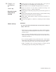
Burner gas pressure
adjustment
The gas pressure is set for the required heat input before the appliance leaves the
factory. Provided that the gas supply to the air heater is in accordance with the
supply pressure described on the appliance data plate, the operating pressure will
not require adjustment. To check the pressure use the following procedure:
* Ascertain from the heater’s data plate the correct operating gas pressure;
* Turn the room thermostat control to its lowest setting;
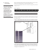
* Remove the screw from the burner pressure test point of the multi-functional
control valve. Connect a manometer to the test point( see figure 10a & 10b);
* Adjust the room thermostat to call for heat i.e. above room ambient tempera-
ture;
* Observe the burner gas pressure on the manometer and compare to the re-
quired pressure on the data plate;
* If necessary, adjust the burner gas pressure. Remove the cover screw (models
035-2 - >100-2) or cover cap (models 008-2 -> 030-2). Turn the regulator
screw anti-clockwise to decrease pressure or clockwise to increase pressure
(see figure 10a & 10b);
* Set room thermostat to lowest setting to turn OFF the burners. Replace the test
point screw/cap and with the main burner OFF, test for gas soundness using a
leak detector fluid.
Reset temperature control/room thermostat to comfort operating level.
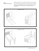
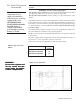
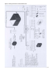
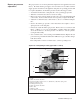
Figure 10a : Honeywell gas valve (types 008-2 -> 030-2)
Legend:
1) Shut-off solenoid valve EV1
2) Pressure regulator setting device, or, alternatively, outlet flow setting screw
3) Inlet pressure test point
4) Outlet pressure test point
5) Shut-off solenoid valve EV2
6) Pilot outlet
7) Main gas outlet
8) Holes (M5) for fixing flanges
7
1
2
8
7
5
3
6
4