
Install Instructions

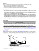
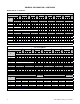
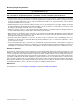
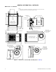
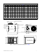
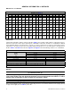
Table Of Contents
- UNIT HEATER INSTALLATION/OPERATION/MAINTENANCE: (MODEL UBX: STANDARD POWER VENT BLOWER TYPE, MODEL UBZ: SEPARATED-COMBUSTION BLOWER TYPE, MODEL UDX: STANDARD POWER VENT FAN TYPE, MODEL UDZ: SEPARATED-COMBUSTION FAN TYPE)
- TABLE OF CONTENTS
- GENERAL INFORMATION
- INSTALLATION
- CONTROLS
- OPERATION
- ADJUSTMENTS
- MAINTENANCE
- Service Checklist
- Maintenance Procedures
- Burner Maintenance
- Burner Orifice Maintenance
- Heat Exchanger Maintenance
- Ignition System Maintenance
- Maintenance of Fan Motor, Fan Blades, and Fan Guard
- Venter Motor and Wheel Assembly Maintenance
- Operating Gas Valve Maintenance
- Pressure Switch Maintenance
- High Temperature Limit Control Maintenance
- Flame Rollout Switch Maintenance (Model UDZ Unit Sizes 030–125 Only)
- Interlock Door Switch Maintenance (Models UBZ and UDZ Only)
- Transformer Maintenance
- Disconnect Switch Replacement (Models UBZ and UDZ Only)
- Vent or Vent/Combustion Air System Maintenance
- TROUBLESHOOTING
- INSTALLATION RECORD (TO BE COMPLETED BY INSTALLER)
- FIGURES
- Figure 1. Heater Throw Patterns (Refer to Table 2 and Table 3)
- Figure 2. Dimensions—Models UBX and UBZ (Refer to Table 4)
- Figure 3. Dimensions—Models UDX and UDZ (Refer to Table 5)
- Figure 4. Confined Space Combustion Air Openings (Refer to Table 8)
- Figure 5. Plugging Unused Suspension Points (Models UBZ and UDZ Only)
- Figure 6. Option CK8 or CK10 Hanger Kit
- Figure 7. Option CK22 Hanger Kit
- Figure 8. Heater Suspension Using Field-Supplied Threaded Rods
- Figure 9. Gas Connections
- Figure 10. Supply Wiring Entrance and Control Connection Terminal Strip
- Figure 11. Circuit Board (DSI Control Module)
- Figure 12. Component Locations (Typical)
- Figure 13. Gas Valve ON/OFF Control
- Figure 14. Pressure Switch
- Figure 15. Gas Valves
- Figure 16. Typical Burner Assembly
- Figure 17. Ignitor Spark Gap
- Figure 18. Fan Blade Positioning and Spacing
- Figure 19. Venter Motor and Wheel Assembly
- Figure 20. Replaceable Components
- Figure 21. DSI Control Module Troubleshooting Flowchart
- TABLES
- Table 1. Related Technical Manuals Available from Factory Distributor
- Table 2. Heater Throw Distances with Standard Horizontal Louvers at Mounting Heights of 5 to 18 Feet
- Table 3. Heater Throw Distances with Standard Horizontal Louvers at Mounting Heights of 1.5 to 5.5 Meters
- Table 4. Dimensions—Models UBX and UBZ
- Table 5. Dimensions—Models UDX and UDZ
- Table 6. Clearances to Combustibles
- Table 7. Unit Weights
- Table 8. Determining Confined Space Combustion Air Requirements
- Table 9. Technical Data for UBX and UBZ Models (Unit Sizes 030–125)
- Table 10. Technical Data for UBX and UBZ Models (Unit Sizes 150–400)
- Table 11. Technical Data for UDX and UDZ Models (Unit Sizes 030–125)
- Table 12. Technical Data for UDX and UDZ Models (Unit Sizes 150–400)
- Table 13. Field-Installed Options
- Table 14. Gas Supply Line Sizes
- Table 15. Gas Connection Sizes
- Table 16. Pressure Switch Settings
- Table 17. Circuit Board (DSI Control Module) Display Codes
- Table 18. Operating Sequence (Normal Heat Cycle)
- Table 19. Operating Sequence (Abnormal Heat Cycle)
- Table 20. Fault Modes
- Table 21. Required Manifold (Outlet) Gas Pressure
- Table 22. Inputs and Capacities by Elevation in US
- Table 23. Inputs and Capacities by Elevation in Canada
- Table 24. Fan Blade Spacing
- Table 25. General Troubleshooting

5
I-UBX-UBZ-UDX-UDZ (04-21) 1034344-0
Warranty
Refer to the limited warranty form in the literature bag provided with the unit. The warranty is void if:
• Wiring is not in accordance with the diagram furnished with the heater.
• The unit is installed without proper clearance to combustible materials.
• A fan model is connected to a duct system or if the air delivery system is modified.
Installation Codes
• These units must be installed in accordance with local building codes. In the absence of local codes, in the United
States, the unit must be installed in accordance with the National Fuel Gas Code, ANSI Z223.1. A Canadian
installation must be in accordance with the CSA B149 Installation Codes. These codes are available from CSA
Information Services, 1-800-463-6727. Local authorities having jurisdiction should be consulted before installation
is made to verify local codes and installation procedure requirements.
• Installations in aircraft hangars should be in accordance with ANSI/NFPA No. 409 (latest edition), Standard for
Aircraft Hangars. Installations in public garages should be in accordance with ANSI/NFPA No. 88A (latest edition),
Standard for Parking Structures. Installations in repair garages should be in accordance with ANSI/NFPA No. 88B
(latest edition), Standard for Repair Garages. In Canada, installations in aircraft hangars should be in accordance
with the requirements of the enforcing authorities, and in public garages, in accordance with CSA B149 codes.
• If the heater is being installed in the Commonwealth of Massachusetts, installation must be performed by a licensed
plumber or licensed gas fitter.
Unit Location
⚠ CAUTION ⚠
• Unit heaters should not be used in an application where the heated space temperature is below 50°F.
Operating under low ambient conditions may cause condensation to form in the heat exchanger.
• Do not locate the heater where it may be exposed to water spray, rain, or dripping water.
• Refer to the venting instructions provided with the unit for venting requirements.
• Refer to the following sections of this manual to determine where to suspend the heater: Heater Throw, Mounting
Height Requirements, Hazards of Chlorine, Dimensions, Clearances, Weights, Combustion Air Requirements,
and Installation.
Heater Throw
Figure 1 shows throw patterns for fan model units. Table 2 and Table 3 list throw distances for standard, adjustable
horizontal louvers on heaters suspended at varying mounting heights. The louver angles listed are relative to the
top of the heater. The throw pattern changes with the addition of optional vertical louvers and/or downturn nozzles.
Z = Distance at which air velocity drops below 50 feet (15.2 meters) per minute
Figure 1. Heater Throw Patterns (Refer to Table 2 and Table 3)