
Install Instructions

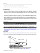
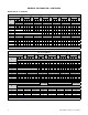
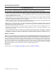
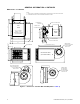
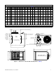
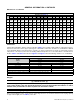
Table Of Contents
- UNIT HEATER INSTALLATION/OPERATION/MAINTENANCE: (MODEL UBX: STANDARD POWER VENT BLOWER TYPE, MODEL UBZ: SEPARATED-COMBUSTION BLOWER TYPE, MODEL UDX: STANDARD POWER VENT FAN TYPE, MODEL UDZ: SEPARATED-COMBUSTION FAN TYPE)
- TABLE OF CONTENTS
- GENERAL INFORMATION
- INSTALLATION
- CONTROLS
- OPERATION
- ADJUSTMENTS
- MAINTENANCE
- Service Checklist
- Maintenance Procedures
- Burner Maintenance
- Burner Orifice Maintenance
- Heat Exchanger Maintenance
- Ignition System Maintenance
- Maintenance of Fan Motor, Fan Blades, and Fan Guard
- Venter Motor and Wheel Assembly Maintenance
- Operating Gas Valve Maintenance
- Pressure Switch Maintenance
- High Temperature Limit Control Maintenance
- Flame Rollout Switch Maintenance (Model UDZ Unit Sizes 030–125 Only)
- Interlock Door Switch Maintenance (Models UBZ and UDZ Only)
- Transformer Maintenance
- Disconnect Switch Replacement (Models UBZ and UDZ Only)
- Vent or Vent/Combustion Air System Maintenance
- TROUBLESHOOTING
- INSTALLATION RECORD (TO BE COMPLETED BY INSTALLER)
- FIGURES
- Figure 1. Heater Throw Patterns (Refer to Table 2 and Table 3)
- Figure 2. Dimensions—Models UBX and UBZ (Refer to Table 4)
- Figure 3. Dimensions—Models UDX and UDZ (Refer to Table 5)
- Figure 4. Confined Space Combustion Air Openings (Refer to Table 8)
- Figure 5. Plugging Unused Suspension Points (Models UBZ and UDZ Only)
- Figure 6. Option CK8 or CK10 Hanger Kit
- Figure 7. Option CK22 Hanger Kit
- Figure 8. Heater Suspension Using Field-Supplied Threaded Rods
- Figure 9. Gas Connections
- Figure 10. Supply Wiring Entrance and Control Connection Terminal Strip
- Figure 11. Circuit Board (DSI Control Module)
- Figure 12. Component Locations (Typical)
- Figure 13. Gas Valve ON/OFF Control
- Figure 14. Pressure Switch
- Figure 15. Gas Valves
- Figure 16. Typical Burner Assembly
- Figure 17. Ignitor Spark Gap
- Figure 18. Fan Blade Positioning and Spacing
- Figure 19. Venter Motor and Wheel Assembly
- Figure 20. Replaceable Components
- Figure 21. DSI Control Module Troubleshooting Flowchart
- TABLES
- Table 1. Related Technical Manuals Available from Factory Distributor
- Table 2. Heater Throw Distances with Standard Horizontal Louvers at Mounting Heights of 5 to 18 Feet
- Table 3. Heater Throw Distances with Standard Horizontal Louvers at Mounting Heights of 1.5 to 5.5 Meters
- Table 4. Dimensions—Models UBX and UBZ
- Table 5. Dimensions—Models UDX and UDZ
- Table 6. Clearances to Combustibles
- Table 7. Unit Weights
- Table 8. Determining Confined Space Combustion Air Requirements
- Table 9. Technical Data for UBX and UBZ Models (Unit Sizes 030–125)
- Table 10. Technical Data for UBX and UBZ Models (Unit Sizes 150–400)
- Table 11. Technical Data for UDX and UDZ Models (Unit Sizes 030–125)
- Table 12. Technical Data for UDX and UDZ Models (Unit Sizes 150–400)
- Table 13. Field-Installed Options
- Table 14. Gas Supply Line Sizes
- Table 15. Gas Connection Sizes
- Table 16. Pressure Switch Settings
- Table 17. Circuit Board (DSI Control Module) Display Codes
- Table 18. Operating Sequence (Normal Heat Cycle)
- Table 19. Operating Sequence (Abnormal Heat Cycle)
- Table 20. Fault Modes
- Table 21. Required Manifold (Outlet) Gas Pressure
- Table 22. Inputs and Capacities by Elevation in US
- Table 23. Inputs and Capacities by Elevation in Canada
- Table 24. Fan Blade Spacing
- Table 25. General Troubleshooting

6
I-UBX-UBZ-UDX-UDZ (04-21) 1034344-0
GENERAL INFORMATION—CONTINUED
Heater Throw—Continued
Table 2. Heater Throw Distances with Standard Horizontal Louvers at Mounting Heights of 5 to 18 Feet
Distance*
Louver
Angle
Distance*
Louver
Angle
Distance*
Louver
Angle
Distance*
Louver
Angle
Distance*
Louver
Angle
Distance*
Louver
Angle
Distance*
Louver
Angle
H
X Y Z X Y Z X Y Z X Y Z X Y Z X Y Z X Y Z
Unit Size
030 045 060 075 100 125 150
5 6 14 30 −21° 7 16 40 −20° 8 18 45 −16° 9 20 57 −14° 9 20 59 −18° 10 22 65 −14° —
8 7 13 26 −39° 9 16 37 −34° 10 18 42 −29° 12 22 54 −25° 11 21 56 −28° 12 23 63 −24° 13 24 73 −26°
10 6 11 22 −52° 9 15 33 −43° 10 17 39 −37° 12 22 52 −32° 12 20 52 −36° 13 24 60 −30° 14 24 69 −32°
12 — 8 12 27 −55° 10 16 34 −46° 12 21 48 −39° 11 19 47 −44° 14 23 57 −36° 14 24 64 −39°
14 — 9 14 29 −56° 12 19 44 −46° 11 17 42 −51° 14 22 53 −43° 14 22 59 −45°
16 — 11 17 38 −54° 10 14 34 −58° 13 20 47 −50° 13 20 53 −51°
18 — 11 17 40 −57° 11 17 44 −58°
H 175 200 225 250 300 350 400
8 15 28 90 −22° 16 30 93 −20° 14 27 86 −24° 16 29 93 −21° 15 28 94 −24° 17 31 105 −20° 18 34 113 −17°
10 17 29 87 −27° 17 31 91 −25° 15 27 82 −30° 17 30 90 −26° 16 28 89 −29° 18 32 103 −25° 20 35 110 −21°
12 18 29 84 −32° 18 31 88 −30° 16 27 78 −35° 18 30 87 −31° 17 28 85 −34° 19 32 98 −30° 21 36 108 −25°
14 18 28 79 −37° 19 30 84 −34° 16 26 73 −41° 18 30 83 −36° 17 27 80 −40° 20 32 95 −34° 23 35 105 −29°
16 18 27 74 −42° 19 29 79 −39° 16 24 67 −47° 19 28 78 −41° 17 25 74 −45° 21 31 90 −38° 23 35 101 −33°
18 17 26 68 −48° 19 28 74 −44° 14 22 60 −53° 18 27 72 −46° 16 24 66 −51° 20 30 85 −43° 23 35 97 −37°
*Distance in feet (see Figure 1).
Table 3. Heater Throw Distances with Standard Horizontal Louvers at Mounting Heights
of 1.5 to 5.5 Meters
Distance*
Louver
Angle
Distance*
Louver
Angle
Distance*
Louver
Angle
Distance*
Louver
Angle
Distance*
Louver
Angle
Distance*
Louver
Angle
H
X Y Z X Y Z X Y Z X Y Z X Y Z X Y Z
Unit Size
030 045 060 075 100 125
1.5 1.8 4.3 9.1 −21° 2.1 4.9 12.2 −20° 2.4 5.5 13.8 −16° 2.7 6.1 17.4 −14° 2.7 6.1 18.0 −18° 3.0 6.7 19.9 −14°
2.4 2.1 4.0 7.9 −39° 2.7 4.9 11.3 −34° 3.0 5.5 12.8 −29° 3.7 6.7 16.5 −25° 3.4 6.4 17.1 −28° 3.7 7.0 19.2 −24°
3.0 1.8 3.4 6.7 −52° 2.7 4.6 10.0 −43° 3.0 5.2 11.9 −37° 3.7 6.7 15.8 −32° 3.7 6.1 15.8 −36° 4.0 7.3 18.3 −30°
3.7 — 2.4 3.7 8.2 −55° 3.0 4.9 10.4 −46° 3.7 6.4 14.6 −39° 3.4 5.8 14.3 −44° 4.3 7.0 17.4 −36°
4.3 — 2.7 4.3 8.8 −56° 3.7 5.8 13.4 −46° 3.4 5.2 12.8 −51° 4.3 6.7 16.1 −43°
4.9 — 3.4 5.2 11.6 −54° 3.0 4.3 10.4 −58° 4.0 6.1 14.3 −50°
5.5 — 3.4 5.2 12.2 −57°
H 150 175 200 225 250 300
2.4 4.0 7.3 22.3 −26° 4.6 8.5 27.4 −22° 4.9 9.1 28.0 −20° 4.3 8.2 26.2 −24° 4.9 8.8 28.3 −21° 4.6 8.5 28.7 −24°
3.0 4.3 7.3 21.0 −32° 5.2 8.8 26.6 −27° 5.2 9.4 27.7 −25° 4.6 8.2 25.0 −30° 5.2 9.1 27.4 −26° 4.9 8.5 27.1 −29°
3.7 4.3 7.3 19.5 −39° 5.5 8.8 25.6 −32° 5.5 9.4 26.8 −30° 4.9 8.2 23.8 −35° 5.5 9.1 26.5 −31° 5.2 8.5 25.9 −34°
4.3 4.3 6.7 18.0 −45° 5.5 8.5 24.1 −37° 5.8 9.1 25.6 −34° 4.9 7.9 22.3 −41° 5.5 9.1 25.3 −36° 5.2 8.2 24.4 −40°
4.9 4.0 6.1 16.2 −51° 5.5 8.2 22.6 −42° 5.8 8.8 24.1 −39° 4.9 7.3 20.4 −47° 5.8 8.5 23.8 −41° 5.2 7.6 22.6 −45°
5.5 3.4 5.2 13.4 −58° 5.2 7.9 20.7 −48° 5.8 8.5 22.6 −44° 4.3 6.7 18.3 −53° 5.5 8.2 21.9 −46° 4.9 7.3 20.1 −51°
Distance*
Louver Angle
Distance*
Louver Angle
H
X Y Z X Y Z
Unit Size
350 400
2.4 5.2 9.4 32.0 −20° 5.5 11.3 34.4 −17°
3.0 5.5 9.8 31.4 −25° 6.1 10.7 33.5 −21°
3.7 5.8 9.8 29.9 −30° 6.4 11.0 32.9 −25°
4.3 6.1 9.8 29.0 −34° 7.0 10.7 32.0 −29°
4.9 6.4 9.4 27.4 −38° 7.0 10.7 30.8 −33°
5.5 6.1 9.1 25.9 −43° 7.0 10.7 26.9 −37°
*Distance in meters (see Figure 1).