
Install Instructions
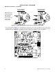
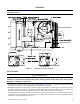
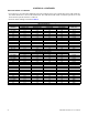

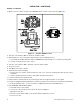
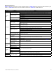
Table Of Contents
- UNIT HEATER INSTALLATION/OPERATION/MAINTENANCE: (MODEL UBX: STANDARD POWER VENT BLOWER TYPE, MODEL UBZ: SEPARATED-COMBUSTION BLOWER TYPE, MODEL UDX: STANDARD POWER VENT FAN TYPE, MODEL UDZ: SEPARATED-COMBUSTION FAN TYPE)
- TABLE OF CONTENTS
- GENERAL INFORMATION
- INSTALLATION
- CONTROLS
- OPERATION
- ADJUSTMENTS
- MAINTENANCE
- Service Checklist
- Maintenance Procedures
- Burner Maintenance
- Burner Orifice Maintenance
- Heat Exchanger Maintenance
- Ignition System Maintenance
- Maintenance of Fan Motor, Fan Blades, and Fan Guard
- Venter Motor and Wheel Assembly Maintenance
- Operating Gas Valve Maintenance
- Pressure Switch Maintenance
- High Temperature Limit Control Maintenance
- Flame Rollout Switch Maintenance (Model UDZ Unit Sizes 030–125 Only)
- Interlock Door Switch Maintenance (Models UBZ and UDZ Only)
- Transformer Maintenance
- Disconnect Switch Replacement (Models UBZ and UDZ Only)
- Vent or Vent/Combustion Air System Maintenance
- TROUBLESHOOTING
- INSTALLATION RECORD (TO BE COMPLETED BY INSTALLER)
- FIGURES
- Figure 1. Heater Throw Patterns (Refer to Table 2 and Table 3)
- Figure 2. Dimensions—Models UBX and UBZ (Refer to Table 4)
- Figure 3. Dimensions—Models UDX and UDZ (Refer to Table 5)
- Figure 4. Confined Space Combustion Air Openings (Refer to Table 8)
- Figure 5. Plugging Unused Suspension Points (Models UBZ and UDZ Only)
- Figure 6. Option CK8 or CK10 Hanger Kit
- Figure 7. Option CK22 Hanger Kit
- Figure 8. Heater Suspension Using Field-Supplied Threaded Rods
- Figure 9. Gas Connections
- Figure 10. Supply Wiring Entrance and Control Connection Terminal Strip
- Figure 11. Circuit Board (DSI Control Module)
- Figure 12. Component Locations (Typical)
- Figure 13. Gas Valve ON/OFF Control
- Figure 14. Pressure Switch
- Figure 15. Gas Valves
- Figure 16. Typical Burner Assembly
- Figure 17. Ignitor Spark Gap
- Figure 18. Fan Blade Positioning and Spacing
- Figure 19. Venter Motor and Wheel Assembly
- Figure 20. Replaceable Components
- Figure 21. DSI Control Module Troubleshooting Flowchart
- TABLES
- Table 1. Related Technical Manuals Available from Factory Distributor
- Table 2. Heater Throw Distances with Standard Horizontal Louvers at Mounting Heights of 5 to 18 Feet
- Table 3. Heater Throw Distances with Standard Horizontal Louvers at Mounting Heights of 1.5 to 5.5 Meters
- Table 4. Dimensions—Models UBX and UBZ
- Table 5. Dimensions—Models UDX and UDZ
- Table 6. Clearances to Combustibles
- Table 7. Unit Weights
- Table 8. Determining Confined Space Combustion Air Requirements
- Table 9. Technical Data for UBX and UBZ Models (Unit Sizes 030–125)
- Table 10. Technical Data for UBX and UBZ Models (Unit Sizes 150–400)
- Table 11. Technical Data for UDX and UDZ Models (Unit Sizes 030–125)
- Table 12. Technical Data for UDX and UDZ Models (Unit Sizes 150–400)
- Table 13. Field-Installed Options
- Table 14. Gas Supply Line Sizes
- Table 15. Gas Connection Sizes
- Table 16. Pressure Switch Settings
- Table 17. Circuit Board (DSI Control Module) Display Codes
- Table 18. Operating Sequence (Normal Heat Cycle)
- Table 19. Operating Sequence (Abnormal Heat Cycle)
- Table 20. Fault Modes
- Table 21. Required Manifold (Outlet) Gas Pressure
- Table 22. Inputs and Capacities by Elevation in US
- Table 23. Inputs and Capacities by Elevation in Canada
- Table 24. Fan Blade Spacing
- Table 25. General Troubleshooting

21
I-UBX-UBZ-UDX-UDZ (04-21) 1034344-0
Table 15. Gas Connection Sizes
Unit Size
Natural Gas Propane
Connection (Inches)*
030–200 1/2 1/2
225–400 3/4 3/4
*Connection size for a standard unit (not gas supply line size).
Electrical Connections
⚠ CAUTION ⚠
• Route wires so that they do not contact the flue wrapper or venter housing.
• If any of the original wire supplied with the appliance must be replaced, it must be replaced with
wiring material having a temperature rating of at least 105°C, except for limit control, flame rollout,
and sensor lead wires which must be rated at 150°C.
NOTES:
• Specific wiring diagrams that include standard and factory-installed options are provided with
the unit. Ensure that all wiring is in accordance with these wiring diagrams.
• A two-stage valve circuit is NOT available on all models.
• All electrical wiring and connections, including electrical grounding MUST be made in accordance with the National
Electric Code ANSI/NFPA No. 70 (latest edition) or, in Canada, with CSA Standard C22.1. In addition, the installer
should be aware of any local ordinances or gas company requirements that might apply.
• Check the rating plate on the heater for the supply voltage and current requirements. A dedicated line voltage
supply with a disconnect switch should be run directly from the main electrical panel to the heater.
• All external wiring must be within approved conduit and have a minimum temperature rise rating of 60°C. Conduit
must be run so as not to interfere with the heater access panel.
• If the installation requires a stepdown transformer (option CG on some models), follow the instructions shipped
with the option package for installing the transformer.
• The supply wiring enters at the rear of the heater, as shown in Figure 10. For UBX and UDX models, the supply
wiring connects directly to leads on the integrated circuit board. For UBZ and UDZ models, the supply wiring
connects to leads located inside a sealed electrical box. To maintain the sealing feature of the electrical box,
always replace the cover plate.
• The terminal strip for 24V control connections is located on the outside of the cabinet at the back of the heater, as
shown in Figure 10. Wires from the terminal strip are factory-wired to the circuit board.
• UDZ and UBZ units have a built-in disconnect switch (20A@115V or 10A@230V rating), as shown in Figure 10.