
Install Instructions
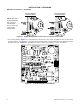
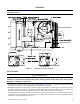
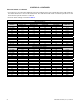

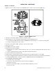
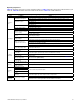
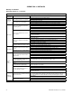
Table Of Contents
- UNIT HEATER INSTALLATION/OPERATION/MAINTENANCE: (MODEL UBX: STANDARD POWER VENT BLOWER TYPE, MODEL UBZ: SEPARATED-COMBUSTION BLOWER TYPE, MODEL UDX: STANDARD POWER VENT FAN TYPE, MODEL UDZ: SEPARATED-COMBUSTION FAN TYPE)
- TABLE OF CONTENTS
- GENERAL INFORMATION
- INSTALLATION
- CONTROLS
- OPERATION
- ADJUSTMENTS
- MAINTENANCE
- Service Checklist
- Maintenance Procedures
- Burner Maintenance
- Burner Orifice Maintenance
- Heat Exchanger Maintenance
- Ignition System Maintenance
- Maintenance of Fan Motor, Fan Blades, and Fan Guard
- Venter Motor and Wheel Assembly Maintenance
- Operating Gas Valve Maintenance
- Pressure Switch Maintenance
- High Temperature Limit Control Maintenance
- Flame Rollout Switch Maintenance (Model UDZ Unit Sizes 030–125 Only)
- Interlock Door Switch Maintenance (Models UBZ and UDZ Only)
- Transformer Maintenance
- Disconnect Switch Replacement (Models UBZ and UDZ Only)
- Vent or Vent/Combustion Air System Maintenance
- TROUBLESHOOTING
- INSTALLATION RECORD (TO BE COMPLETED BY INSTALLER)
- FIGURES
- Figure 1. Heater Throw Patterns (Refer to Table 2 and Table 3)
- Figure 2. Dimensions—Models UBX and UBZ (Refer to Table 4)
- Figure 3. Dimensions—Models UDX and UDZ (Refer to Table 5)
- Figure 4. Confined Space Combustion Air Openings (Refer to Table 8)
- Figure 5. Plugging Unused Suspension Points (Models UBZ and UDZ Only)
- Figure 6. Option CK8 or CK10 Hanger Kit
- Figure 7. Option CK22 Hanger Kit
- Figure 8. Heater Suspension Using Field-Supplied Threaded Rods
- Figure 9. Gas Connections
- Figure 10. Supply Wiring Entrance and Control Connection Terminal Strip
- Figure 11. Circuit Board (DSI Control Module)
- Figure 12. Component Locations (Typical)
- Figure 13. Gas Valve ON/OFF Control
- Figure 14. Pressure Switch
- Figure 15. Gas Valves
- Figure 16. Typical Burner Assembly
- Figure 17. Ignitor Spark Gap
- Figure 18. Fan Blade Positioning and Spacing
- Figure 19. Venter Motor and Wheel Assembly
- Figure 20. Replaceable Components
- Figure 21. DSI Control Module Troubleshooting Flowchart
- TABLES
- Table 1. Related Technical Manuals Available from Factory Distributor
- Table 2. Heater Throw Distances with Standard Horizontal Louvers at Mounting Heights of 5 to 18 Feet
- Table 3. Heater Throw Distances with Standard Horizontal Louvers at Mounting Heights of 1.5 to 5.5 Meters
- Table 4. Dimensions—Models UBX and UBZ
- Table 5. Dimensions—Models UDX and UDZ
- Table 6. Clearances to Combustibles
- Table 7. Unit Weights
- Table 8. Determining Confined Space Combustion Air Requirements
- Table 9. Technical Data for UBX and UBZ Models (Unit Sizes 030–125)
- Table 10. Technical Data for UBX and UBZ Models (Unit Sizes 150–400)
- Table 11. Technical Data for UDX and UDZ Models (Unit Sizes 030–125)
- Table 12. Technical Data for UDX and UDZ Models (Unit Sizes 150–400)
- Table 13. Field-Installed Options
- Table 14. Gas Supply Line Sizes
- Table 15. Gas Connection Sizes
- Table 16. Pressure Switch Settings
- Table 17. Circuit Board (DSI Control Module) Display Codes
- Table 18. Operating Sequence (Normal Heat Cycle)
- Table 19. Operating Sequence (Abnormal Heat Cycle)
- Table 20. Fault Modes
- Table 21. Required Manifold (Outlet) Gas Pressure
- Table 22. Inputs and Capacities by Elevation in US
- Table 23. Inputs and Capacities by Elevation in Canada
- Table 24. Fan Blade Spacing
- Table 25. General Troubleshooting

30
I-UBX-UBZ-UDX-UDZ (04-21) 1034344-0
Table 19. Operating Sequence (Abnormal Heat Cycle)
Abnormal
Function
Condition Action
Interrupted
thermostat
call for heat
Thermostat demand for heat is
removed before flame is recognized
Control runs venter motor for post-purge period
All outputs are deenergized
Thermostat demand for heat is
removed after successful ignition
Control deenergizes gas valve
Control runs venter motor through post-purge period
Control runs fan/blower motor on heat speed for selected delay OFF time
Ignition retry
Flame is not established on first trial
for ignition period
Control deenergizes gas valve
Venter motor remains energized for 10-second inter-purge period
Spark and gas valve are re-energized
Control initiates another trial for ignition
Flame is not established on second
trial for ignition
Control deenergizes gas valve
Control runs fan/blower motor on heat speed
Venter motor remains energized
Fan/blower motor deenergizes after selected delay OFF period and spark and gas
valve are re-energized
Control initiates another trial for ignition (this fan delay is self-healing feature for open
auxiliary limit switch)
Flame is not established on third trial
for ignition
Control deenergizes gas valve
Venter motor remains energized for 10-second inter-purge period
Spark and gas valve are re-energized
Control initiates another trial for ignition
Flame is not established on fourth trial
for ignition (initial try plus three re-tries)
Control deenergizes gas valve and proceeds to lockout
SSD displays “L” to indicate ignition failure lockout
Limit switch*
Limit switch is open and call for heat is
present
Control deenergizes gas valve
Control runs venter motor and runs fan/blower motor on heat speed
Control is in soft lockout (SSD displays “L”) before returning to normal operation
Limit switch re-closes or call for heat is
not present
Control runs venter motor through post-purge period
Control runs fan/blower motor on heat speed through selected delay OFF period
Pressure
switch
operation
Pressure switch opens before trial for
ignition period
Venter motor runs through 2-second pressure switch recognition delay
Control deenergizes gas valve
Control runs venter motor through post-purge period
Control restarts heat cycle at pressure switch proving state if call for heat still exists
Pressure switch opens for less than 2
seconds during trial for ignition period
(shall not interrupt heat cycle)
Control deenergizes gas valve while pressure switch is open
Pressure switch opens after successful
ignition
Control deenergizes gas valve
Flame is lost before end of 2-second
pressure switch recognition delay
Control responds to loss of flame
Pressure switch remains open for 2
seconds and flame remains
Control deenergizes gas valve
Control runs venter motor through post-purge period
Control runs fan/blower motor on heat speed through selected delay OFF period
When fan OFF delay ends, fan/blower motor is deenergized, and heat cycle begins if
call for heat still exists
Continuous
fan operation
Thermostat calls for continuous fan (G)
without call for heat
Fan motor is energized after 0.25-second delay (this brief ON delay allows terminal
G to energize slightly before terminal Y and allows external changeover relay to
switch from terminal G to terminal W without causing momentary glitches in fan/
blower output
Fan remains energized as long as call for fan remains without call for heat
Thermostat calls for heat (W) during
continuous fan operation
Fan/blower is deenergized
Call for fan is ignored during lockout
*The limit switch is ignored unless a call for heat is present (terminal W energized).
OPERATION—CONTINUED
Startup—Continued
Operating Sequences—Continued