
Vertical Louver Kit Instructions
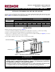
Table Of Contents

Revision: CP-UB-UD-UEZ-VL (03-21) 1036173-0
VERTICAL LOUVER KIT INSTALLATION FOR UNIT HEATERS
Supersedes: — (Original Version)
OPTION CD1 FOR MODELS UBX, UBZ, UDX, UDZ, AND UEZ
Vertical louvers are designed to direct discharge air to provide a wider throw pattern. This vertical louver option
applies to separated-combustion unit heater models UBX, UBZ, UDX, UDZ, and UEZ. Ensure that all components
listed in Table 1 are available before beginning installation.
⚠ DANGER ⚠
• Improper installation, adjustment, alteration, service, or maintenance can cause property
damage, injury, or death. Read the installation, operation, and maintenance instructions
thoroughly before installing or servicing this equipment.
• Installation should be done by a qualified agency in accordance with these instructions and
in compliance with all codes and requirements of authorities having jurisdiction.
DO NOT DESTROY. PLEASE READ CAREFULLY. KEEP IN A SAFE PLACE FOR FUTURE REFERENCE.
Table 1. Option CD1 Kit Components
Component
Unit Size (UBX, UBZ, UDX, UDZ) Unit Size (UEZ)
030, 045 060, 075 100, 125 150, 175, 200 225, 250 300, 350, 400 130, 180 260, 310
PN (Quantity)
Kit package 1036298 (1) 1036299 (1) 1036300 (1) 1036301 (1) 1036302 (1) 1036303 (1) 1036304 (1) 1036303 (1)
Frame, louver 1028413 (1) 1028433 (1) 1028443 (1) 1033695 (1) 1033715 (1) 1033728 (1) 1033902 (1) 1033728 (1)
Louver 1028418 (5) 1028434 (5) 1028441 (5) 1033904 (8) 1033961 (8) 1033730 (8) 1033904 (8) 1033730 (8)
Spring, compression 195046 (5) 195046 (8) 195046 (8)
INSTALLATION
Install the vertical louver kit as follows (see Figure 1):
1. If heater is installed, turn OFF gas and electric power. Allow time for louvers to cool before proceeding.
2. Remove each horizontal louver by pushing louver toward spring to release louver.
3. Remove door on right side of unit to access screws that secure face plate assembly (see Figure 1) to front of
unit. Remove screws and remove face plate assembly.
4. In face plate opening for louver frame, remove screws from face plate.
Figure 1. Typical Face Plate Assembly and Louver Frame
FACE PLATE ASSEMBLY
FACE PLATE
LOUVER FRAME