
UDZ Venting Instructions
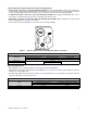
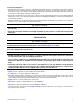
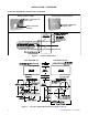
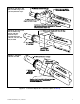
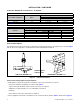
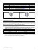
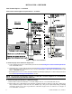
Table Of Contents
- VENTING INSTRUCTIONS FOR UNIT HEATERS (MODEL UBZ: SEPARATED-COMBUSTION BLOWER TYPE AND MODEL UDZ: SEPARATED-COMBUSTION FAN TYPE)
- GENERAL INFORMATION
- INSTALLATION
- APPENDIX: INSTRUCTIONS FOR ATTACHING DOUBLE-WALL TYPE B VENT PIPE TO SINGLE-WALL PIPE
- FIGURES
- Figure 1. Typical Combustion Air Inlet and Venter Outlet Connections
- Figure 2. Concentric Adapter Box
- Figure 3. Concentric Adapter Box Dimensions (Refer to Table 4)
- Figure 4. Concentric Adapter Box Connections (Refer to Table 4)
- Figure 5. Vent Terminal Options
- Figure 6. Option CC2 Components
- Figure 7. Option CC2 Installation
- Figure 8. Concentric Adapter Box Brackets
- Figure 9. Combustion Air Pipe Installation
- Figure 10. Combustion Air Pipe Through Roof
- Figure 11. Combustion Air Inlet and Vent Terminal
- Figure 12. Option CC6 Components
- Figure 13. Option CC6 Installation
- TABLES
- Table 1. Combustion Air Inlet and Venter Outlet Connection Sizes
- Table 2. Concentric (Outdoor) Pipe Sizes
- Table 3. Diameter and Length of Pipe from Heater to Concentric Adapter Box
- Table 4. Vent Pipe Opening Diameter
- Table 5. Concentric Adapter Box Vent Pipe Sizes
- Table 6. Vertical Vent Terminal/Combustion Air Package (Option CC2) Components
- Table 7. Minimum Spacing Between Center Lines of Vertical Vent Pipes
- Table 8. Horizontal Vent Terminal/Combustion Air Package (Option CC6) Components
- Table 9. Minimum Clearance Requirements for Horizontal Vent Termination Location

10
CP-UBZ-UDZ-VENT (02-21) 1034632-0
INSTALLATION—CONTINUED
Vent Terminal Options—Continued
Vertical Vent Terminal (Option CC2) Installation—Continued
Shaded area represents
required continuous
(no joints) section of
vent pipe. Section of
pipe may extend higher.
Vent Pipe
Rear
View
Side View
Figure 7. Option CC2 Installation
2. Install vent pipe and combustion air pipe runs:
a. Connect piping to heater in accordance with specifications listed in Venting and Combustion Air Requirements
section and subsections.
b. Seal all joints in accordance with specifications listed in Joint Connection and Sealing Requirements section.
Due to high temperature considerations, do not enclose exhaust pipe or place pipe closer than 6 inches (152
mm) to combustible material.
c. Extend piping runs close to roof at location selected in step 1 and support piping in accordance with specifications
listed in Vent System Support Requirements section.
NOTE: The vent pipe will extend through the roof after the concentric adapter box is installed. The
indoor combustion air pipe will end at the box.
3. Cut hole through outside wall for combustion air pipe.
a. Ensure that location and orientation of concentric adapter box are correct and mark and cut hole.
b. Ensure that hole accommodates 6-inch (152 mm) combustion air pipe for unit sizes 030–125 or 8-inch (203-
mm) combustion air pipe for unit sizes 150–400. Thimble may or may not be required depending on building
construction and/or local codes. Larger diameter combustion air pipe serves as clearance for vent pipe on
non-combustible construction.