
UDZ Venting Instructions
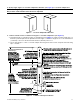
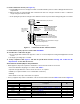
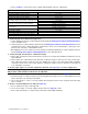
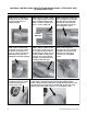


Table Of Contents
- VENTING INSTRUCTIONS FOR UNIT HEATERS (MODEL UBZ: SEPARATED-COMBUSTION BLOWER TYPE AND MODEL UDZ: SEPARATED-COMBUSTION FAN TYPE)
- GENERAL INFORMATION
- INSTALLATION
- APPENDIX: INSTRUCTIONS FOR ATTACHING DOUBLE-WALL TYPE B VENT PIPE TO SINGLE-WALL PIPE
- FIGURES
- Figure 1. Typical Combustion Air Inlet and Venter Outlet Connections
- Figure 2. Concentric Adapter Box
- Figure 3. Concentric Adapter Box Dimensions (Refer to Table 4)
- Figure 4. Concentric Adapter Box Connections (Refer to Table 4)
- Figure 5. Vent Terminal Options
- Figure 6. Option CC2 Components
- Figure 7. Option CC2 Installation
- Figure 8. Concentric Adapter Box Brackets
- Figure 9. Combustion Air Pipe Installation
- Figure 10. Combustion Air Pipe Through Roof
- Figure 11. Combustion Air Inlet and Vent Terminal
- Figure 12. Option CC6 Components
- Figure 13. Option CC6 Installation
- TABLES
- Table 1. Combustion Air Inlet and Venter Outlet Connection Sizes
- Table 2. Concentric (Outdoor) Pipe Sizes
- Table 3. Diameter and Length of Pipe from Heater to Concentric Adapter Box
- Table 4. Vent Pipe Opening Diameter
- Table 5. Concentric Adapter Box Vent Pipe Sizes
- Table 6. Vertical Vent Terminal/Combustion Air Package (Option CC2) Components
- Table 7. Minimum Spacing Between Center Lines of Vertical Vent Pipes
- Table 8. Horizontal Vent Terminal/Combustion Air Package (Option CC6) Components
- Table 9. Minimum Clearance Requirements for Horizontal Vent Termination Location

7. Install inlet guard:
a. Position inlet guard over end of combustion air pipe in accordance with Figure 13.
b. Secure inlet guard to inlet air pipe using four 1/2-inch-long screws provided.
8. Install terminal-end vent pipe:
NOTE: The length of the terminal-end vent pipe is determined by the installation within maximum
and minimum requirements. The vent pipe extending through the concentric adapter box, through
the combustion air inlet pipe, and above the combustion air inlet air pipe must be one piece with-
out joints. The connection to the vent pipe run must be a maximum of 6 inches (152 mm) from the
heater side of the box.
a. Refer to Figure 13 to determine lengths of each pipe segment and to calculate total length required.
b. Ensure that terminal-end vent pipe is in proper flow direction and slide end of pipe through box.
c. Position vent pipe so that it extends 3–6 inches (76–152 mm) past end of combustion air pipe and no more
than 6 inches (152 mm) out of box toward heater.
d. Connect terminal-end vent pipe to vent pipe run no more than 6 inches (152 mm) from heater.
9. Install exhaust grill:
a. Position exhaust grill over end of vent pipe in accordance with Figure 13.
b. Secure exhaust grill to end of vent pipe using four 1/2-inch-long screws provided.
c. Seal vent pipe to concentric adapter box.
d. Verify that terminal-end section of vent pipe has slight downward pitch of 1/4-inch (6-mm) per foot (305 mm)
toward outside.
e. Seal completely around circumference of pipe and opening of box using silicone sealant.
10. Install indoor section of combustion air pipe:
a. Secure single-wall combustion air pipe run to collar on concentric adapter box using sheet metal screws.
b. Seal pipe joint using tape or sealant.
11. Verify compliance with Figure 13 and with all specifications listed in Venting and Combustion Air
Requirements section and subsections.
17
CP-UBZ-UDZ-VENT (02-21) 1034632-0