
UDZ Installation Manual
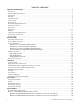
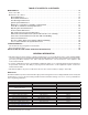
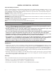
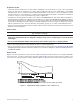
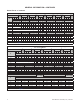
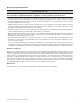
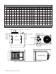
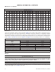
Table Of Contents
- UNIT HEATER INSTALLATION/OPERATION/MAINTENANCE (MODEL UBX: STANDARD POWER VENT BLOWER TYPE, MODEL UBZ: SEPARATED-COMBUSTION BLOWER TYPE, MODEL UDX: STANDARD POWER VENT FAN TYPE, AND MODEL UDZ: SEPARATED-COMBUSTION FAN TYPE)
- TABLE OF CONTENTS
- GENERAL INFORMATION
- INSTALLATION
- CONTROLS
- OPERATION
- ADJUSTMENTS
- MAINTENANCE
- Service Checklist
- Maintenance Procedures
- Burner Maintenance
- Burner Orifice Maintenance
- Heat Exchanger Maintenance
- Ignition System Maintenance
- Maintenance of Fan Motor, Fan Blades, and Fan Guard
- Venter Motor and Wheel Assembly Maintenance
- Operating Gas Valve Maintenance
- Pressure Switch Maintenance
- High Temperature Limit Control Maintenance
- Flame Rollout Switch Maintenance (Model UDZ Unit Sizes 030–125 Only)
- Interlock Door Switch Maintenance (Models UBZ and UDZ Only)
- Transformer Maintenance
- Disconnect Switch Replacement (Models UBZ and UDZ Only)
- Vent or Vent/Combustion Air System Maintenance
- TROUBLESHOOTING
- INSTALLATION RECORD (TO BE COMPLETED BY INSTALLER)
- FIGURES
- Figure 1. Heater Throw Patterns (Refer to Table 2 and Table 3)
- Figure 2. Dimensions—Models UBX and UBZ (Refer to Table 4)
- Figure 3. Dimensions—Models UDX and UDZ (Refer to Table 5)
- Figure 4. Confined Space Combustion Air Openings (Refer to Table 8)
- Figure 5. Plugging Unused Suspension Points (Models UBZ and UDZ Only)
- Figure 6. Option CK10 Hanger Kit
- Figure 7. Option CK22 Hanger Kit
- Figure 8. Heater Suspension Using Field-Supplied Threaded Rods
- Figure 9. Gas Connections
- Figure 10. Supply Wiring Entrance and Control Connection Terminal Strip
- Figure 11. Circuit Board (DSI Control Module)
- Figure 12. Component Locations (Typical)
- Figure 13. Gas Valve ON/OFF Control
- Figure 14. Pressure Switch
- Figure 15. Gas Valves
- Figure 16. Typical Burner Assembly
- Figure 17. Ignitor Spark Gap
- Figure 18. Fan Blade Positioning and Spacing
- Figure 19. Venter Motor and Wheel Assembly
- Figure 20. Replaceable Components
- Figure 21. DSI Control Module Troubleshooting Flowchart
- TABLES
- Table 1. Related Technical Manuals Available from Factory Distributor
- Table 2. Heater Throw Distances with Standard Horizontal Louvers at Mounting Heights of 5 to 18 Feet
- Table 3. Heater Throw Distances with Standard Horizontal Louvers at Mounting Heights of 1.5 to 5.5 Meters
- Table 4. Dimensions—Models UBX and UBZ
- Table 5. Dimensions—Models UDX and UDZ
- Table 6. Clearances to Combustibles
- Table 7. Unit Weights
- Table 8. Determining Confined Space Combustion Air Requirements
- Table 9. Technical Data for UBX and UBZ Models (Unit Sizes 030–125)
- Table 10. Technical Data for UBX and UBZ Models (Unit Sizes 150–400)
- Table 11. Technical Data for UDX and UDZ Models (Unit Sizes 030–125)
- Table 12. Technical Data for UDX and UDZ Models (Unit Sizes 150–400)
- Table 13. Field-Installed Options
- Table 14. Gas Supply Line Sizes
- Table 15. Gas Connection Sizes
- Table 16. Pressure Switch Settings
- Table 17. Operating Sequence (Normal Heat Cycle)
- Table 18. Operating Sequence (Abnormal Heat Cycle)
- Table 19. Fault Modes
- Table 20. Required Manifold (Outlet) Gas Pressure
- Table 21. Inputs and Capacities by Elevation in US
- Table 22. Inputs and Capacities by Elevation in Canada
- Table 23. Fan Blade Spacing
- Table 24. General Troubleshooting
- Table 25. Circuit Board (DSI Control Module) Display Codes

3
UBX-UBZ-UDX-UDZ-IOM (03-22) 1034344-C
TABLE OF CONTENTS—CONTINUED
MAINTENANCE...........................................................................37
Service Checklist.........................................................................37
Maintenance Procedures ..................................................................37
Burner Maintenance ....................................................................37
Burner Orifice Maintenance ..............................................................40
Heat Exchanger Maintenance ............................................................40
Ignition System Maintenance .............................................................40
Maintenance of Fan Motor, Fan Blades, and Fan Guard ........................................41
Venter Motor and Wheel Assembly Maintenance .............................................42
Operating Gas Valve Maintenance ........................................................43
Pressure Switch Maintenance ............................................................43
High Temperature Limit Control Maintenance ................................................43
Flame Rollout Switch Maintenance (Model UDZ Unit Sizes 030–125 Only) .........................44
Interlock Door Switch Maintenance (Models UBZ and UDZ Only).................................44
Transformer Maintenance ...............................................................44
Disconnect Switch Replacement (Models UBZ and UDZ Only)...................................44
Vent or Vent/Combustion Air System Maintenance ............................................44
TROUBLESHOOTING ......................................................................44
Unit Troubleshooting Using DSI Control Module.................................................44
General Troubleshooting...................................................................46
INSTALLATION RECORD (TO BE COMPLETED BY INSTALLER)...................................48
GENERAL INFORMATION
• This unit heater has been tested for capacity and efficiency so as to provide many years of safe and dependable
comfort providing it is properly installed and maintained. With regular maintenance, this unit will operate satisfactorily
year after year. Abuse, improper use, and/or improper maintenance can shorten the life of the appliance and
create unsafe hazards.
• To achieve optimum performance and minimize equipment failure, it is recommended that periodic maintenance
be performed on this unit. The ability to properly perform maintenance on this equipment requires certain tools
and mechanical skills.
• This manual applies only to the models listed. Accessories referenced may not apply to all models.
References
Both this installation/operation manual and the appropriate venting instructions are shipped with the heater. Verify that
the literature is correct for the heater being installed. If either manual is missing or incorrect, contact your Distributor
before beginning installation.
Table 1. Related Technical Manuals Available from Factory Distributor
Type Form
PN*
Replacement parts UBX-UBZ-UDX-UDZ-RPL 1034346
Venting instructions**
UBX-UDX-VENTING 1034631
UBZ-UDZ-VENTING 1034632
Vertical louver kit installation UBX-UBZ-UDX-UDZ-UEZ-CD1 1036173
Downturn nozzle kit installation UBX-UBZ-UDX-UDZ-UEZ-CD2,3,4,5 1036421
Duct flange kit installation UBX-UBZ-CD9 1036171
Polytube adapter kit installation UBX-UBZ-CD11 1036422
Ceiling suspension kit installation UDX-UDZ-CK22 1037006
Gas conversion kit installation UBX-UBZ-UDX-UDZ-GC 1034364
Vent/combustion air kit installation OPT-CC2-CC6 205892
Relay kits for multiple heater control OPT-CL31-CL32 102247
Heat exchanger gasket kit installation UBX-UBZ-UDX-UDZ-UEZ-HX 1037154
*Also available at www.reznorhvac.com.
**BOTH this installation manual and the correct venting instructions are REQUIRED for the installation of this unit heater.