
UDZ Installation Manual
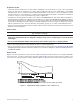
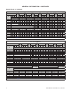
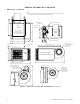
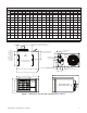
Table Of Contents
- UNIT HEATER INSTALLATION/OPERATION/MAINTENANCE (MODEL UBX: STANDARD POWER VENT BLOWER TYPE, MODEL UBZ: SEPARATED-COMBUSTION BLOWER TYPE, MODEL UDX: STANDARD POWER VENT FAN TYPE, AND MODEL UDZ: SEPARATED-COMBUSTION FAN TYPE)
- TABLE OF CONTENTS
- GENERAL INFORMATION
- INSTALLATION
- CONTROLS
- OPERATION
- ADJUSTMENTS
- MAINTENANCE
- Service Checklist
- Maintenance Procedures
- Burner Maintenance
- Burner Orifice Maintenance
- Heat Exchanger Maintenance
- Ignition System Maintenance
- Maintenance of Fan Motor, Fan Blades, and Fan Guard
- Venter Motor and Wheel Assembly Maintenance
- Operating Gas Valve Maintenance
- Pressure Switch Maintenance
- High Temperature Limit Control Maintenance
- Flame Rollout Switch Maintenance (Model UDZ Unit Sizes 030–125 Only)
- Interlock Door Switch Maintenance (Models UBZ and UDZ Only)
- Transformer Maintenance
- Disconnect Switch Replacement (Models UBZ and UDZ Only)
- Vent or Vent/Combustion Air System Maintenance
- TROUBLESHOOTING
- INSTALLATION RECORD (TO BE COMPLETED BY INSTALLER)
- FIGURES
- Figure 1. Heater Throw Patterns (Refer to Table 2 and Table 3)
- Figure 2. Dimensions—Models UBX and UBZ (Refer to Table 4)
- Figure 3. Dimensions—Models UDX and UDZ (Refer to Table 5)
- Figure 4. Confined Space Combustion Air Openings (Refer to Table 8)
- Figure 5. Plugging Unused Suspension Points (Models UBZ and UDZ Only)
- Figure 6. Option CK10 Hanger Kit
- Figure 7. Option CK22 Hanger Kit
- Figure 8. Heater Suspension Using Field-Supplied Threaded Rods
- Figure 9. Gas Connections
- Figure 10. Supply Wiring Entrance and Control Connection Terminal Strip
- Figure 11. Circuit Board (DSI Control Module)
- Figure 12. Component Locations (Typical)
- Figure 13. Gas Valve ON/OFF Control
- Figure 14. Pressure Switch
- Figure 15. Gas Valves
- Figure 16. Typical Burner Assembly
- Figure 17. Ignitor Spark Gap
- Figure 18. Fan Blade Positioning and Spacing
- Figure 19. Venter Motor and Wheel Assembly
- Figure 20. Replaceable Components
- Figure 21. DSI Control Module Troubleshooting Flowchart
- TABLES
- Table 1. Related Technical Manuals Available from Factory Distributor
- Table 2. Heater Throw Distances with Standard Horizontal Louvers at Mounting Heights of 5 to 18 Feet
- Table 3. Heater Throw Distances with Standard Horizontal Louvers at Mounting Heights of 1.5 to 5.5 Meters
- Table 4. Dimensions—Models UBX and UBZ
- Table 5. Dimensions—Models UDX and UDZ
- Table 6. Clearances to Combustibles
- Table 7. Unit Weights
- Table 8. Determining Confined Space Combustion Air Requirements
- Table 9. Technical Data for UBX and UBZ Models (Unit Sizes 030–125)
- Table 10. Technical Data for UBX and UBZ Models (Unit Sizes 150–400)
- Table 11. Technical Data for UDX and UDZ Models (Unit Sizes 030–125)
- Table 12. Technical Data for UDX and UDZ Models (Unit Sizes 150–400)
- Table 13. Field-Installed Options
- Table 14. Gas Supply Line Sizes
- Table 15. Gas Connection Sizes
- Table 16. Pressure Switch Settings
- Table 17. Operating Sequence (Normal Heat Cycle)
- Table 18. Operating Sequence (Abnormal Heat Cycle)
- Table 19. Fault Modes
- Table 20. Required Manifold (Outlet) Gas Pressure
- Table 21. Inputs and Capacities by Elevation in US
- Table 22. Inputs and Capacities by Elevation in Canada
- Table 23. Fan Blade Spacing
- Table 24. General Troubleshooting
- Table 25. Circuit Board (DSI Control Module) Display Codes

4
UBX-UBZ-UDX-UDZ-IOM (03-22) 1034344-C
GENERAL INFORMATION—CONTINUED
Important Safety Information
Please read all information in this manual thoroughly and become familiar with the capabilities and use of your
appliance before attempting to operate or maintain this unit. Pay attention to all dangers, warnings, cautions, and
notes highlighted in this manual. Safety markings should not be ignored and are used frequently throughout to
designate a degree or level of seriousness.
DANGER: A danger statement describes a potentially hazardous situation that if not avoided, will result in severe
personal injury or death and/or property damage.
WARNING: A warning statement describes a potentially hazardous situation that if not avoided, can result in severe
personal injury and/or property damage.
CAUTION: A caution statement describes a potentially hazardous situation that if not avoided, can result in minor
or moderate personal injury and/or property damage.
NOTE: A note provides important information that should not be ignored.
⚠ WARNING ⚠
• Gas-fired appliances are not designed for use in hazardous atmospheres containing flammable
vapors or combustible dust, in atmospheres containing chlorinated or halogenated hydrocarbons,
or in applications with airborne silicone substances.
• Should overheating occur, or the gas supply control system fail to shut off the flow of gas, shut
off the manual gas valve to the unit before shutting off the electrical supply.
• Do not use this appliance if any part has been under water. Immediately call a qualified service
technician to inspect the appliance and replace any gas control that has been under water.
• Installation should be done by a qualified agency in accordance with these instructions. The
qualified service agency installing this heater is responsible for the installation.
• This appliance is not intended for use by persons with reduced physical, sensory, or mental
capabilities or lack of experience and knowledge, unless they have been given supervision or
instruction concerning use of the appliance by a person responsible for their safety.
• Children should be supervised to ensure that they do not play with the appliance.
Certification
• Unit sizes 030, 045, 060, 075, 100, and 125 are design-certified by the Canadian Standards Association for use in
residential, industrial, and commercial installations. Utility heaters certified for residential use are intended for the
heating of non-living spaces that are attached to or part of a structure that contains space for family living quarters.
They are not intended to be the primary source of heat in residential applications or to be used in sleeping quarters.
• Unit sizes 150, 175, 200, 225, 250, 300, 350, and 400 are design-certified by the Canadian Standards Association
for use in industrial and commercial installations only.
• All models and unit sizes are available for use with either natural or propane gas. The type of gas, the gas input
rate, and the electrical supply requirement are shown on the heater rating plate. Check the rating plate to verify
that the heater is appropriate for the installation site.
Warranty
Refer to the limited warranty form in the literature bag provided with the unit. The warranty is void if:
• Wiring is not in accordance with the diagram furnished with the heater.
• The unit is installed without proper clearance to combustible materials.
• A fan model is connected to a duct system or if the air delivery system is modified.