
UDZ Installation Manual
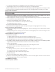
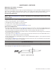
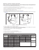
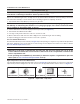
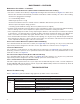
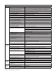
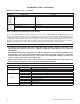
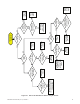
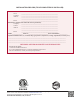
Table Of Contents
- UNIT HEATER INSTALLATION/OPERATION/MAINTENANCE (MODEL UBX: STANDARD POWER VENT BLOWER TYPE, MODEL UBZ: SEPARATED-COMBUSTION BLOWER TYPE, MODEL UDX: STANDARD POWER VENT FAN TYPE, AND MODEL UDZ: SEPARATED-COMBUSTION FAN TYPE)
- TABLE OF CONTENTS
- GENERAL INFORMATION
- INSTALLATION
- CONTROLS
- OPERATION
- ADJUSTMENTS
- MAINTENANCE
- Service Checklist
- Maintenance Procedures
- Burner Maintenance
- Burner Orifice Maintenance
- Heat Exchanger Maintenance
- Ignition System Maintenance
- Maintenance of Fan Motor, Fan Blades, and Fan Guard
- Venter Motor and Wheel Assembly Maintenance
- Operating Gas Valve Maintenance
- Pressure Switch Maintenance
- High Temperature Limit Control Maintenance
- Flame Rollout Switch Maintenance (Model UDZ Unit Sizes 030–125 Only)
- Interlock Door Switch Maintenance (Models UBZ and UDZ Only)
- Transformer Maintenance
- Disconnect Switch Replacement (Models UBZ and UDZ Only)
- Vent or Vent/Combustion Air System Maintenance
- TROUBLESHOOTING
- INSTALLATION RECORD (TO BE COMPLETED BY INSTALLER)
- FIGURES
- Figure 1. Heater Throw Patterns (Refer to Table 2 and Table 3)
- Figure 2. Dimensions—Models UBX and UBZ (Refer to Table 4)
- Figure 3. Dimensions—Models UDX and UDZ (Refer to Table 5)
- Figure 4. Confined Space Combustion Air Openings (Refer to Table 8)
- Figure 5. Plugging Unused Suspension Points (Models UBZ and UDZ Only)
- Figure 6. Option CK10 Hanger Kit
- Figure 7. Option CK22 Hanger Kit
- Figure 8. Heater Suspension Using Field-Supplied Threaded Rods
- Figure 9. Gas Connections
- Figure 10. Supply Wiring Entrance and Control Connection Terminal Strip
- Figure 11. Circuit Board (DSI Control Module)
- Figure 12. Component Locations (Typical)
- Figure 13. Gas Valve ON/OFF Control
- Figure 14. Pressure Switch
- Figure 15. Gas Valves
- Figure 16. Typical Burner Assembly
- Figure 17. Ignitor Spark Gap
- Figure 18. Fan Blade Positioning and Spacing
- Figure 19. Venter Motor and Wheel Assembly
- Figure 20. Replaceable Components
- Figure 21. DSI Control Module Troubleshooting Flowchart
- TABLES
- Table 1. Related Technical Manuals Available from Factory Distributor
- Table 2. Heater Throw Distances with Standard Horizontal Louvers at Mounting Heights of 5 to 18 Feet
- Table 3. Heater Throw Distances with Standard Horizontal Louvers at Mounting Heights of 1.5 to 5.5 Meters
- Table 4. Dimensions—Models UBX and UBZ
- Table 5. Dimensions—Models UDX and UDZ
- Table 6. Clearances to Combustibles
- Table 7. Unit Weights
- Table 8. Determining Confined Space Combustion Air Requirements
- Table 9. Technical Data for UBX and UBZ Models (Unit Sizes 030–125)
- Table 10. Technical Data for UBX and UBZ Models (Unit Sizes 150–400)
- Table 11. Technical Data for UDX and UDZ Models (Unit Sizes 030–125)
- Table 12. Technical Data for UDX and UDZ Models (Unit Sizes 150–400)
- Table 13. Field-Installed Options
- Table 14. Gas Supply Line Sizes
- Table 15. Gas Connection Sizes
- Table 16. Pressure Switch Settings
- Table 17. Operating Sequence (Normal Heat Cycle)
- Table 18. Operating Sequence (Abnormal Heat Cycle)
- Table 19. Fault Modes
- Table 20. Required Manifold (Outlet) Gas Pressure
- Table 21. Inputs and Capacities by Elevation in US
- Table 22. Inputs and Capacities by Elevation in Canada
- Table 23. Fan Blade Spacing
- Table 24. General Troubleshooting
- Table 25. Circuit Board (DSI Control Module) Display Codes

46
UBX-UBZ-UDX-UDZ-IOM (03-22) 1034344-C
TROUBLESHOOTING—CONTINUED
General Troubleshooting—Continued
Table 25. Circuit Board (DSI Control Module) Display Codes
Display Code Status Display Code Indication
Steady
— Normal operation—no call for heat
0 Ignition sequence active
H Normal operation—call for heat (strong flame)
Flashing
2 Normal operation—call for heat (weak flame)
L Lockout from failed ignition or flame loss
3 Pressure switch is not closed within 30 seconds of venter motor energizing
4 Pressure switch is closed before venter motor is energized
5 Limit switch or rollout open
6 Undesired flame
7 Polarity reversed
Steady Off Internal fault/power failure
Unit Troubleshooting Using DSI Control Module
The seven-segment display on the DSI control module (refer to Circuit Board (DSI Control Module) section) may
be used to troubleshoot the unit. The control module monitors the operation of the heater, and the display indicates
normal operation and various abnormal conditions. If the heater fails to operate properly, check this display (refer
to Table 25) to determine the cause and/or to eliminate certain causes. Remove and reapply power to the control
module to view the last five fault codes stored in its memory—the most recent to least recent fault codes will be
displayed. See Figure 21 for a flowchart for troubleshooting the unit using the DSI control module.
NOTES:
• If troubleshooting indicates that repair of the DSI control module is required, note that its only
replaceable part is the fuse (see Figure 11), which is a type ATC or ATO 3A fuse, color code violet
(PN 201685).
• IMPORTANT: When using a multimeter to troubleshoot the 24V circuit, place the multimeter’s test
leads into the connectors located on the ignition control. Do not remove connectors or terminals
from the electrical components. Doing so can result in misinterpreted readings caused by the
control module’s fault mode monitoring circuits.
• Remove and reapply power to the control module to view the last five fault codes stored in its
memory. The most recent to least recent fault codes will be displayed.
Table 24. General Troubleshooting
Symptom Probable Cause Remedy
Fan or
venter
motor turns
ON and
OFF while
burner is
operating
1. Motor overload device cycling ON and
OFF
Check motor load against motor rating plate—replace motor if needed
Fan or
venter
motor cuts
out on
overload
1. Low or high voltage supply Correct electric supply
2. Defective motor Replace motor
3. Poor airflow Clean motor, fan, and fan guard
—Continued