
UDZ Venting Instructions
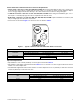
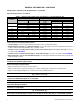
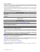
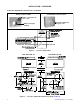
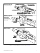
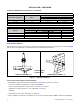
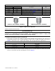
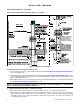
Table Of Contents
- VENTING INSTRUCTIONS FOR UNIT HEATERS (MODEL UBZ: SEPARATED-COMBUSTION BLOWER TYPE AND MODEL UDZ: SEPARATED-COMBUSTION FAN TYPE)
- GENERAL INFORMATION
- INSTALLATION
- APPENDIX: INSTRUCTIONS FOR ATTACHING DOUBLE-WALL TYPE B VENT PIPE TO SINGLE-WALL PIPE
- FIGURES
- Figure 1. Typical Combustion Air Inlet and Venter Outlet Connections
- Figure 2. Concentric Adapter Box
- Figure 3. Concentric Adapter Box Dimensions (Refer to Table 4)
- Figure 4. Concentric Adapter Box Connections (Refer to Table 4)
- Figure 5. Vent Terminal Options
- Figure 6. Option CC2 Components
- Figure 7. Option CC2 Installation
- Figure 8. Concentric Adapter Box Brackets
- Figure 9. Combustion Air Pipe Installation
- Figure 10. Combustion Air Pipe Through Roof
- Figure 11. Combustion Air Inlet and Vent Terminal
- Figure 12. Option CC6 Components
- Figure 13. Option CC6 Installation
- TABLES
- Table 1. Combustion Air Inlet and Venter Outlet Connection Sizes
- Table 2. Concentric (Outdoor) Pipe Sizes
- Table 3. Diameter and Length of Pipe from Heater to Concentric Adapter Box
- Table 4. Vent Pipe Opening Diameter
- Table 5. Concentric Adapter Box Vent Pipe Sizes
- Table 6. Vertical Vent Terminal/Combustion Air Package (Option CC2) Components
- Table 7. Minimum Spacing Between Center Lines of Vertical Vent Pipes
- Table 8. Horizontal Vent Terminal/Combustion Air Package (Option CC6) Components
- Table 9. Minimum Clearance Requirements for Horizontal Vent Termination Location

Table 3. Diameter and Length of Pipe from Heater to Concentric Adapter Box
Unit Size
Diameter (Inches (mm)) Feet (Meters)
Vent Pipe Inlet Air Pipe
Maximum Vent
Length
Equivalent Straight Length*
90-Degree Elbow 45-Degree Elbow
030, 045
3 (76) 15 (4.6)
2 (0.6) 1 (0.3)
4 (102) 10 (3)
060
3 (76) 25 (7.6) 3 (0.9) 1.5 (0.5)
4 (102) 15 (4.6) 1.5 (0.5) 1 (0.3)
075 4 (102) 25 (7.6) 3 (0.9) 1.5 (0.5)
100, 125 4 (102) 35 (10.7) 4 (1.2) 2 (0.6)
150 5 (127) 6 (152) 30 (9.1) 3 (0.9) 1.5 (0.5)
175 5 (127) 6 (152) 30 (9.1) 3 (0.9) 2 (0.6)
200, 225, 250 5 (127) 6 (152) 40 (12.2) 4 (1.2) 2 (0.6)
300 6 (152) 45 (13.7) 4 (1.2) 2 (0.6)
350, 400 6 (152) 45 (13.7) 5 (1.5) 2.5 (0.8)
*Add all straight sections and equivalent lengths for elbows—the total combined length must not exceed the maximum vent length.
GENERAL INFORMATION—CONTINUED
Venting and Combustion Air Requirements—Continued
Pipe Size Requirements—Continued
Joint Connection and Sealing Requirements
• Category III pipe: follow the pipe manufacturer’s instructions for joining and sealing.
• Single-wall pipe (vent pipe or combustion air pipe): secure slip-fit pipe connections using sheet metal screws
or rivets. Seal all joints with aluminum tape or silicone sealant.
• Terminal section of double-wall vent pipe (vertical vent terminal option CC2 only) to vent cap: connect in
accordance with APPENDIX.
• Terminal section of double-wall vent pipe to single-wall vent pipe: connect in accordance with APPENDIX.
• When joining two sections of double-wall vent pipe: follow the pipe manufacturer’s instructions for joining and
sealing vent pipe sections.
NOTE: Joints connecting double-wall pipe apply only to commercial/industrial installations with
a vertical vent terminal (option CC2).
Vent System Support Requirements
• Support horizontal runs every six feet (1.8 meters).
• Support vertical runs category III vent pipe in accordance with the pipe manufacturer’s requirements.
• Support vertical single-wall pipe in accordance with accepted industry practice.
⚠ CAUTION ⚠
• Do not rely on the heater to support either horizontal or vertical vent pipe.
• Use non-combustible supports on vent pipe.
NOTE: The vertical vent terminal pipe does not attach to the concentric adapter box and must be
supported during installation.
Clearance to Combustibles
⚠ DANGER ⚠
Do not enclose the vent pipe or place it closer than 6 inches (152 mm) to combustible material.
4
CP-UBZ-UDZ-VENT (02-21) 1034632-0