
UDZ Venting Instructions
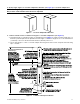
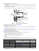
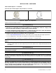
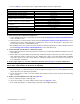
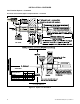
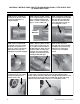
Table Of Contents
- VENTING INSTRUCTIONS FOR UNIT HEATERS (MODEL UBZ: SEPARATED-COMBUSTION BLOWER TYPE AND MODEL UDZ: SEPARATED-COMBUSTION FAN TYPE)
- GENERAL INFORMATION
- INSTALLATION
- APPENDIX: INSTRUCTIONS FOR ATTACHING DOUBLE-WALL TYPE B VENT PIPE TO SINGLE-WALL PIPE
- FIGURES
- Figure 1. Typical Combustion Air Inlet and Venter Outlet Connections
- Figure 2. Concentric Adapter Box
- Figure 3. Concentric Adapter Box Dimensions (Refer to Table 4)
- Figure 4. Concentric Adapter Box Connections (Refer to Table 4)
- Figure 5. Vent Terminal Options
- Figure 6. Option CC2 Components
- Figure 7. Option CC2 Installation
- Figure 8. Concentric Adapter Box Brackets
- Figure 9. Combustion Air Pipe Installation
- Figure 10. Combustion Air Pipe Through Roof
- Figure 11. Combustion Air Inlet and Vent Terminal
- Figure 12. Option CC6 Components
- Figure 13. Option CC6 Installation
- TABLES
- Table 1. Combustion Air Inlet and Venter Outlet Connection Sizes
- Table 2. Concentric (Outdoor) Pipe Sizes
- Table 3. Diameter and Length of Pipe from Heater to Concentric Adapter Box
- Table 4. Vent Pipe Opening Diameter
- Table 5. Concentric Adapter Box Vent Pipe Sizes
- Table 6. Vertical Vent Terminal/Combustion Air Package (Option CC2) Components
- Table 7. Minimum Spacing Between Center Lines of Vertical Vent Pipes
- Table 8. Horizontal Vent Terminal/Combustion Air Package (Option CC6) Components
- Table 9. Minimum Clearance Requirements for Horizontal Vent Termination Location

2. Install vent pipe and combustion air pipe runs:
a. Connect piping to heater in accordance with specifications listed in Venting and Combustion Air Requirements
section and subsections.
b. Seal all joints in accordance with specifications listed in Venting and Combustion Air Requirements section
and subsections. Due to high temperature considerations, do not enclose exhaust pipe or place pipe closer
than 6 inches (152 mm) to combustible material.
c. Extend piping runs close to wall at location selected in step 1 and support piping in accordance with specifications
listed in Venting and Combustion Air Requirements section and subsections.
3. Cut hole through outside wall for combustion air pipe.
a. Ensure that outside wall construction thickness is between 1 inch (25 mm) minimum and 48 inches (1,219
mm) maximum.
b. Ensure that hole accommodates 6-inch (152 mm) combustion air pipe for unit sizes 030–125 or 8-inch (203-
mm) combustion air pipe for unit sizes 150–400. Thimble may or may not be required depending on building
construction and/or local codes. Larger diameter combustion air pipe serves as clearance for vent pipe on
non-combustible construction.
4. Secure longer angles on concentric adapter box brackets (see Figure 8) to concentric adapter box.
NOTE: The longer angle of the concentric adapter box bracket has five 7/32-inch holes that allow
the position of the bracket on the box to be adjusted.
5. Connect outside section of combustion air pipe to concentric adapter box (see Figure 9):
a. Determine length of combustion air pipe by measuring 1) bracket length from box to wall, 2) wall thickness, 3)
plus 4–16 inches (102–406 mm) beyond wall.
b. Secure inlet air pipe to collar of concentric adapter box using sheet metal screws. Seal joint and seam using
tape or sealant.
6. Secure concentric adapter box to wall (see Figure 13):
a. Insert combustion air pipe out through wall.
b. Secure short angles of concentric adapter box brackets (see Figure 8) to wall.
c. Seal or flash inlet air pipe on outside using sealant and/or field-supplied flashing.
Table 9. Minimum Clearance Requirements for Horizontal Vent Termination Location
Component/Structure Minimum Clearance, All Directions Unless Specified (Feet (Meters))
Forced air inlet within 10 feet (3.1 meters)*
3 (0.9) above
Combustion air inlet of another appliance 6 (1.8)
Mechanical air supply inlet to any building Canada: 6 (1.8)
Any building opening (door, window, or gravity air inlet)
4 (1.2) horizontal and below
1 (0.3) above
Gas meter,** electric meter, and relief equipment
US: 4 (1.2) horizontal
Canada: 6 (1.8) horizontal
Gas regulator**
US: 3 (0.9) horizontal
Canada: 6 (1.8) horizontal
Adjoining building or parapet 6 (1.8)
Adjacent public walkway 7 (2.1) above
Grade (ground level) 3 (0.9) above
*Does not apply to the inlet of a direct vent appliance.
**Do not terminate the vent directly above a gas meter or service regulator.
15
CP-UBZ-UDZ-VENT (02-21) 1034632-0
e. Refer to Table 9 to ensure that location complies with minimum clearance requirements.