
UDZ Venting Instructions
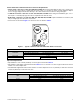
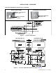
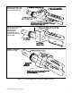
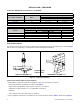
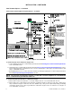
Table Of Contents
- VENTING INSTRUCTIONS FOR UNIT HEATERS (MODEL UBZ: SEPARATED-COMBUSTION BLOWER TYPE AND MODEL UDZ: SEPARATED-COMBUSTION FAN TYPE)
- GENERAL INFORMATION
- INSTALLATION
- APPENDIX: INSTRUCTIONS FOR ATTACHING DOUBLE-WALL TYPE B VENT PIPE TO SINGLE-WALL PIPE
- FIGURES
- Figure 1. Typical Combustion Air Inlet and Venter Outlet Connections
- Figure 2. Concentric Adapter Box
- Figure 3. Concentric Adapter Box Dimensions (Refer to Table 4)
- Figure 4. Concentric Adapter Box Connections (Refer to Table 4)
- Figure 5. Vent Terminal Options
- Figure 6. Option CC2 Components
- Figure 7. Option CC2 Installation
- Figure 8. Concentric Adapter Box Brackets
- Figure 9. Combustion Air Pipe Installation
- Figure 10. Combustion Air Pipe Through Roof
- Figure 11. Combustion Air Inlet and Vent Terminal
- Figure 12. Option CC6 Components
- Figure 13. Option CC6 Installation
- TABLES
- Table 1. Combustion Air Inlet and Venter Outlet Connection Sizes
- Table 2. Concentric (Outdoor) Pipe Sizes
- Table 3. Diameter and Length of Pipe from Heater to Concentric Adapter Box
- Table 4. Vent Pipe Opening Diameter
- Table 5. Concentric Adapter Box Vent Pipe Sizes
- Table 6. Vertical Vent Terminal/Combustion Air Package (Option CC2) Components
- Table 7. Minimum Spacing Between Center Lines of Vertical Vent Pipes
- Table 8. Horizontal Vent Terminal/Combustion Air Package (Option CC6) Components
- Table 9. Minimum Clearance Requirements for Horizontal Vent Termination Location

7
CP-UBZ-UDZ-VENT (02-21) 1034632-0
Figure 4. Concentric Adapter Box Connections (Refer to Table 4)
DETAIL A: Unit Sizes 030,
045, and 060 Using 3-Inch
(76 mm) Diameter Pipes
DETAIL B: Unit Sizes 030,
045, and 060 Using
4-Inch (102 mm)
Diameter Pipes
and Unit Sizes 075,
100, 125, 150, 175, 200,
225, and 250
DETAIL C: Unit Sizes
300, 350, and 400