
Downturn Nozzle Kit Instructions
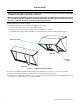
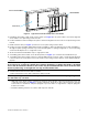
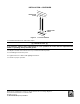
Table Of Contents

3
CP-UB-UD-UEZ-DN (03-21) 1036421-0
Figure 2. Typical Face Plate Assembly and Louver Frame
5. If installing option CD4 or CD5, position louver frame (see Figure 2) in face plate outlet so that holes align and
secure frame to face plate using screws from kit.
6. Position downturn nozzle assembly in face plate so that holes align and secure nozzle to face plate using screws
from kit.
7. Install nozzle blockoff (see Figure 1) and secure to face plate using screws from kit.
8. Position face plate assembly with downturn nozzle assembly so that holes align and secure both assemblies—
through face plate opening on left side, top, bottom and through door opening on right side—to front of unit using
screws from kit. Replace door on right side of unit.
9. Secure nozzle blockoff installed in step 7 to right panel of unit.
10. If installing option CD3 or CD5, secure blockoff panel (see Figure 1) to nozzle blockoff installed in step 7.
11. If installing option CD3 or CD5, position second assembled nozzle section in outlet of nozzle already attached
to heater. Secure second nozzle section to first nozzle section using screws from kit to create downturn with two
sections.
NOTE: Before installing the louvers, note the louver curve and determine how the louvers should
be positioned to provide the optimal throw pattern. Depending on where the heater is installed
and on the desired airflow direction, the louvers may be installed with their curves all in the same
direction (either way) or the right half one way and the left the other.
12. Install vertical louvers in louver frame as follows:
a. On notched end of louver, slide compression spring over tab.
NOTE: Depending on the desired throw pattern, the end of the louver with the spring can go either
into the frame top or bottom.
b. With wider louver blade facing in toward heat exchanger, push tab with compression spring into hole in top
or bottom louver frame (see Figure 3)—spring compresses. Insert tab on other end of louver into opposite
louver frame. For left airflow, compress spring into top louver frame. For right airflow, compress spring into
bottom louver frame.
c. Install all remaining louvers in accordance with steps 12a and 12b.
FACE PLATE ASSEMBLY
FACE PLATE
LOUVER FRAM
E