
User Manual


Scorpion I IIIAR Reader
2
Copyright 2001
RF Code, Inc.
4 Scorpion I Reader
The Scorpion I Reader contains the internal components of an RF Code Scorpion I
Reader and an Ethernet Client Bridge and is housed in a 12” x 8.5” x 2” painted,
aluminum chassis with screw-on cover. The reader works with Scorpion I Tags
that periodically transmit an encoded radio signal identity. The reader decodes
each tag’s signal and sends that information to the host processor, using the
Ethernet Client Bridge as a communication interface to the local area network
(LAN).
4.1 Scorpion I Reader Physical I/O
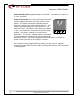
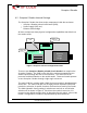
Figure 1 Scorpion I Reader (Front View)
Each Scorpion I Reader
Antenna Post
(A & B) supplies an RF signal to the
two parallel radio receivers in the Scorpion I Reader. Reference Paragraph
4.3, Page 7 for antenna positioning for optimum performance. The antenna
input impedance is 50 ohms nominal.
Charge Indicator
is on while the reader is in operation. The
light
may or may
not be on while the power is applied, even when the reader’s power switch is
off.
On- Ready Indicator
light, when illuminated, indicates the Scorpion I Reader
has power applied through the external power connector and the power switch
is on.
Tag Activity Indicator
light is used for two purposes: to show the status of
the reader while in standby mode and to show tag detections while in active
mode.
Fast Charge
On - Ready
Tag Activity
Charge
indicator
Power on
indicator
Tag Activity
indicator
Wireless Ethernet
Antenna
Scorpion I
Reader Antenna
A
B