
User Manual


Scorpion I Reader
Copyright 2001
RF Code, Inc.
5
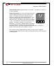
4.2 Scorpion I Reader Internal Settings
The Scorpion I Reader has three major components inside the enclosure:
•
Scorpion I Reader printed circuit board (PCB);
•
Power Supply PCB; and,
•
Ethernet Client Bridge.
All three components have physical configuration capabilities that affect how
the reader works.
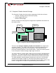
Figure 3 Scorpion I Internal Configuration Points
There are two
Scorpion I Reader printed circuit boards
that comprise the
Scorpion I Reader. The PCB on the side of the enclosure extends the two
antenna posts through the side of the enclosure. The main PCB is the
processor and data interface to the outside world. These two boards operate
as one Scorpion I Reader through a right angle connector.
The main PCB has a power switch (SW2) that must remain in the
On
position,
all the time. The main PCB also has an eight-position Dipswitch (SW1) that
permits the selection of specific functions and baud rates used by the reader.
The SW1 Dipswitch factory setting is switches two and six on and all other
switches off as shown in Figure 3. Each time the reader is turned on, it is
restored to the default settings which is determined by this switch. Most of the
reader’s configuration controls are implemented by serial download
3
4
5
6
7
2
8
1
Scorpion I
Power Supply
Ethernet
Client
Bridge
3M
6M
11M
22M
6H
3H
45M
12H
Power Switch
SW2
Function Select
Switch SW1
Watchdog Time
Select P2