
User's Manual


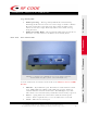


Table Of Contents
- User Manual
- Contents
- 1 – Introduction
- 2 – Hardware
- Front View – LED Indicators
- Rear View – Data Connections
- Antennas – Positioning
- Environmental Limits
- Tag Positioning
- 3 – Firmware
- File System
- Upgradeable Firmware
- Reader Setup
- Configuration Files & Default Settings
- 4 – Troubleshooting
- A – List of Acronyms
- B – Index
- C – FCC Compliance

© Copyright 2003 RF Code, Inc. All rights reserved. UM-C2020-R02-20030422.
No copying of this material is allowed without prior written permission. Page 5 of 27.
USER MANUAL – Mantis™ II 433.92MHz Reader
5
2 – Hardware
The Mantis™ II 433.92MHz Reader is housed in a 5 x 5 x 1.5 inch (12.7 x
12.7 x 3.81 cm) metal chassis and contains the internal components of a
RFID Reader combined with connections to allow for both Ethernet and serial
port connectivity.
Front View – LED Indicators
Figure 2.1 – Mantis™ II 433.92MHz Reader (front view)
shown with standard ¼-wave helical antennae.
Three LEDs are mounted on the front of the Mantis™ II 433.92MHz
Reader.
• Unlabeled LED – This LED is used for a feature that is not
implemented in this version of the Reader.
• On-Ready LED – This LED indicates the Reader has power applied
through an external power adapter.
• Tag Activity LED – This LED is used for two purposes: (1) to show
the status of the Reader while in standby mode and (2) to show Tag
detections while in operation.