
User's Manual


CS-490 NA BESPA User Manual Rev2.0 - Part # 11900-439 Aug 2020
6
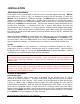
Ethernet
The Ethernet LAN connection uses the industry standard RJ-45 8P8C modular connector. A
suitable Ethernet cable fitted with an RJ-45 plug is connected to the BESPA Array Antenna
as shown in Figure 1. The BESPA is factory programmed with a fixed IP address which is
shown on the label adjacent to the Ethernet connector.
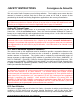
Non-Ionizing Radiation
This unit incorporates a Radio Frequency Transmitter and should therefore be installed and
operated so as to avoid exposure of any persons to unsafe emissions. A minimum
separation distance of 34cm must be maintained at all times between antenna and all
persons. See FCC Radiation Exposure Statement in the Safety Instructions section of this
guide.
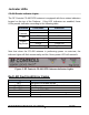
Usable Frequency Range in US and Canada
For use in USA, Canada, and other North American countries, this device is factory
programmed to operate in ISM 902MHz – 928MHz band and cannot be operated on other
frequency bands. Model#: CS-490 NA
MULTIPLE BESPA UNITS CONFIGURED AS AN ITCS
Figure 3 shows how two or more CS-490 BESPA units may be connected via an Ethernet
network to an ITCS Location Processor. One Location Processor and multiple distributed
BESPAs operate collaboratively to form RF Controls’ Intelligent Tracking and Control System
(ITCS™). In this example two BESPA units have been attached to the network.
Combinations of the various model BESPA units may be mixed and matched as required to
suit a particular installation. The RF Controls Technical Manual provides details on how to
install, configure and calibrate an ITCS.
Figure 3 Intelligent Tracking and Control System comprising a number of
BESPA units connected via POE Ethernet Network to a Location Processor