
User's Manual


13715 Alton Pkwy • Irvine • CA • 92618
Tel: 949.610.0008 • Fax: 949.610.0009
www.rfdigital.com • sales@rfdigital.com
7
© Copyright,
RF Digital Corp.
9/2/2010 12:02 PM
Patents Pending
RoHS
FCC APPROVED
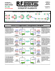
RFDP8
RFDANT
RFD21743
Eval Board
RFD21773
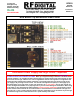
The 8 different modes of the RFDP8 Application Protocol are selected using the 3-position dip-switch S5 shown in
the examples below. The 3 inputs have resistor pull-downs to ground, so when the switch is in its OFF (open)
position, there is a low (0) on the input. When the switch is in its ON (closed) position, it connects the input to +V,
which produces a high (1).
The proper way to read binary is MSB on the left and LSB on the right. Switch manufacturers label the switches
from left to right and furthermore they commonly start with 1 rather then 0. So careful attention needs to be given
to identify the switch positions. The binary is read from MSB to LSB, rather then LSB to MSB as shown in the
examples below. To remove all doubt, only follow the examples shown below.
RFDP8 Mode Selector Switch
Mode 0
Active RFID
Transmitter
OFF OFF OFF
Mode 1
3-Input
Switch Logic
Transmitter
ON
OFF OFF
Mode 2
Serial UART
Transceiver
9600-8N1
ON
OFF OFF
Mode 3
Serial UART
Transceiver
9600-8N1
Network
ON ON
OFF
Mode 4
3-Output Switch
Logic Receiver
500ms Hang Time
ON
OFF OFF
Mode 5
3-Output Switch
Logic Receiver
500ms Hang Time
Network
ON ON
OFF
Mode 6
3-Output Switch
Logic Receiver
20ms Hang Time
ON ON
OFF
Mode 7
3-Output Switch
Logic Receiver
20ms Hang Time
Network
ON ON ON