SATELLITE TV OPERATION / TECHNICAL MANUAL 31 March 2014
The Eagle Manual 2
The Eagle Manual I ndex Warning ....................... 4 Mount Definitions ........................ 5 Controller Views ....................... 6 Configuration and Software Versions ....................... 8 Menus and Operations ....................... 9 Connector Wiring Diagram ....................... 11 Raising the ODU Using a 12 VDC Source ....................... 11 SWM DirecTV Block Diagram ....................... 12 Foot Print and Clearances .......................
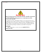
The Eagle Manual WARNING Make all electrical and coax connections from the controller to the mount and LNB's BEFORE applying power to, or connecting the satellite receiver to the controller. Note: When the controller is turned OFF it continues to pass voltage from the receiver to the LNB if the receiver remains connected to 110 AC power. Shorting the coax at any time during installation may cause damage to either the Controller or the DiSEqC Switch (if installed).
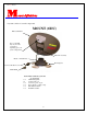
The Eagle Manual M ount definitions A system consists of several components MOUNT (ODU) Reflector/Parabola Note: Your LNB may vary from the one pictured depending upon your system configuration. LNB Arm Assembly Mount or Azimuth Base Mounting Feet Connector Weather Cover Clam Shell Items included with the system and are not shown.
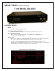
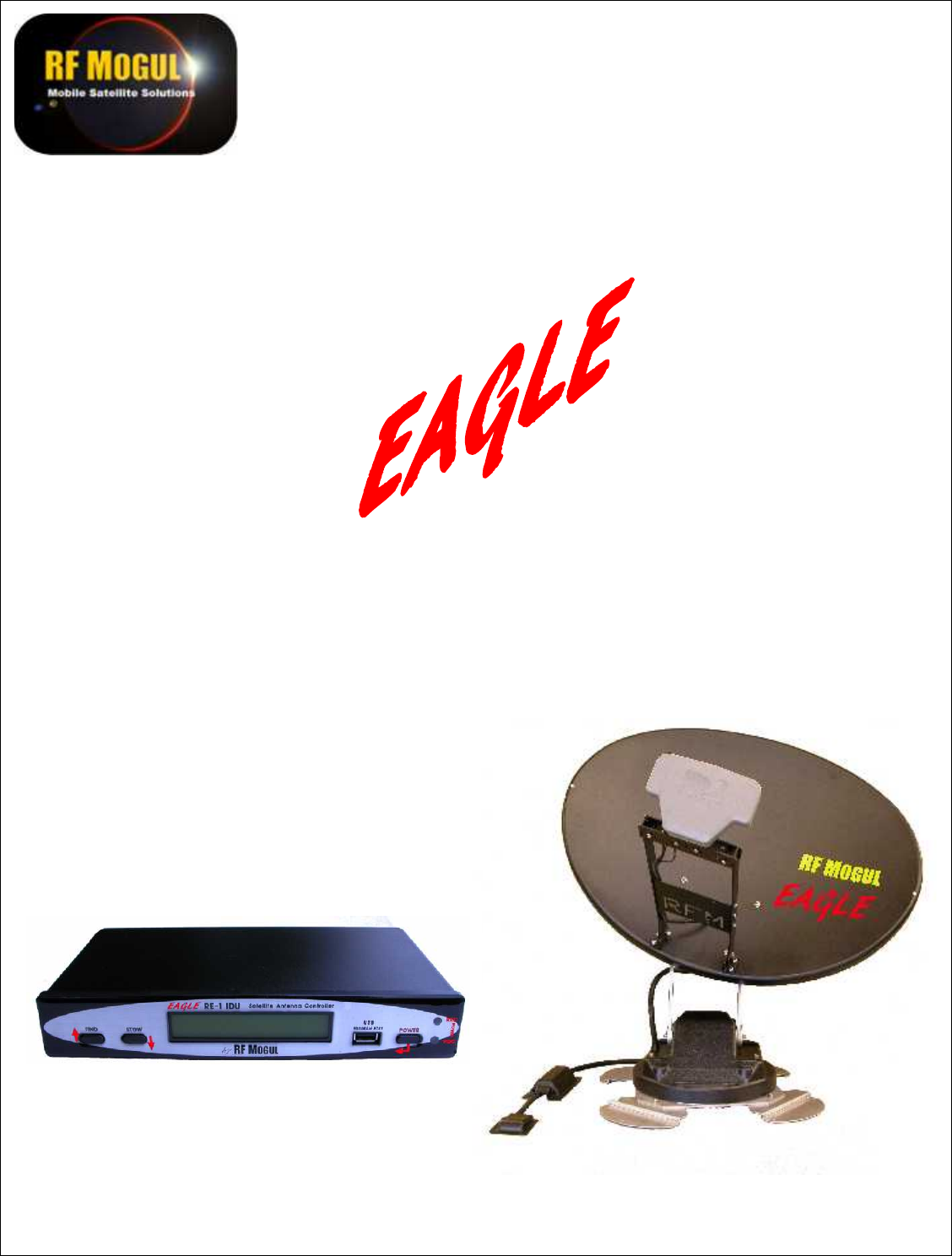
The Eagle Manual C ontroller Views FRONT VIEW Definitions and Usage CONTROLLER (IDU) FIND Directs the system to "FIND" Satellites. Navigates through the menu and selects a particular function. STOW Directs the system to "STOW" the mount and prepare it for travel Navigates through the menu and selects a particular function. LCD Display Displays the actions of the system. USB Programming Port Used for upgrading firmware. POWER Will turn controller ON and OFF. Navigates through the Menu options.
The Eagle Manual REAR VIEW Definitions and Usage CONTROLLER (IDU) To REC To LNB CONNECTIONS POWER 12 VDC 7 amp (power supply provided). CONTROL CABLE CONNECTION: Termination of the 12 wires of the control cable to the controller takes place here. TO SATELLITE RECEIVER This is a coax pass-through connection to your satellite receiver (Satellite IN). It is optional except for DirecTV SWM. TO ODU LNB: This is a coax connection to the Antenna's LNB.
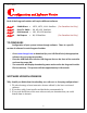
The Eagle Manual C onfigurations and Software Version Each of the Program Providers will require different software EAGLE -1 EAGLE -2 EAGLE -3 EAGLE -4 SHAW Direct = DirecTV SWM = Dish Network = Bell Express = 107.3, 107.3, 111.1 Satellites 99, 101, 103 Satellites 110, 119, 129 Satellites 81, 92 Satellites (For Canadian Use Only) (For Canadian Use Only) TO CONFIGURE Configuration of your system is done through software. There is a specific version of software for each Program Provider.
The Eagle Manual M enu Options Menus and Operation Your controller is menu driven. By selecting a particular menu you can perform many functions besides just "SEARCHING for satellite". TO SEARCH Press the Power button o Displayed will be the.... System configuration (software configuration) EAGLE 1 SHAW (Triple Satellite xKu LNB) EAGLE 2 DIRECTV (SWM 3 LNB) EAGLE 3 DISH NETWORK (Triple Satellite 1000.2 LNB) EAGLE 4 BELL TV (Triple Satellite 1000.2 LNB) Version of software i.e. 14.02.
The Eagle Manual 6: move skew - Selecting this option and pressing and holding the appropriate button will manually move your dish in skew (Up arrow right side DOWN, Down arrow left side DOWN 7: test dish - Selecting this option will move the dish in all axis for one complete cycle 8: temperature - Selecting this options will display current operating temperature of its operating environment.
The Eagle Manual C onnector Wiring Diagram Wiring the 12 Pin Controller Connector RAISING THE ODU USING A 12 VDC SOURCE TO RAISE THE MOUNT WITH A BATTERY Pin Used Color How Used Where 1 = 2 = 3 = 4 = 5 = 6 = 7 = 8 = 9 = 10 = 11 = 12 = BLACK BROWN RED ORANGE YELLOW GREEN BLUE VIOLET GRAY WHITE PINK TAN Motor Motor Motor Motor Motor Motor Count Count Count -Azimuth +Azimuth -Elevation +Elevation - Skew +Skew Azimuth Elevation Skew Touch the following wires from the control cable directly to a drill
The Eagle Manual SWM Block Diagram INSET Note: The SWM LNB has 8 channels available. Each DVR takes 2 channels (one coax). A non DVR uses one channel (one coax). You may use any combination of receivers until you use up all 8 channels. Example: A HR34 uses 5 channels leaving 3 channels available. IDU Receiver line Note: See bottom of IDU for wiring instructions. 4 Port splitter shown.
The Eagle Manual F ootprint and Clearances 39 Inches 8 1/2 Inches 13 1/2 Inches Distance for installing LNB Landing Plate Rotational clearance from center rotation point is 18 inches when dish is elevated and rotating. This is a safety zone.
The Eagle Manual R eturning Parts to the Factory Parts returned to the factory must contain a Return Material Authorization (RMA) which will be provided by the RF Mogul Technical Support Department at the time of troubleshooting. This will ensure proper accountability of returned equipment or parts. Make sure that the following information is contained on your shipment.