Satellite TV Nomad SD/SD2 USER GUIDE Software Version 116 or higher ALL RIGHTS RESERVED 901-Nomad SD2 Manual Rev 20 Dec ‘10
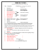
INDEX DEFINITIONS 3 FEATURES 4 FRONT View REAR View 5 6 OPERATION Testing the Dish Finding the Satellite Stowing the Dish SD Memory Cards Firmware Upgrade Log Files Error Message Definition 7 7 7 8 8 9 9 ERROR CODES 10 PROGRAMMING (Configuration) Using the Front Panel Entering into Configuration Mode 11 SETTING SERVICE AND MOUNT TYPE 12 SHOW MODE SETTINGS 13 ROOT DIRECTORY EXPLANATION 14 MOUNT DEFINITIONS 16 SENSORS 17 WIRE SCHEMATIC 18 MOUNT CLEARANCE 19 LIMITED WARRANTY 20 NOTE
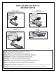
MOUNT ROTATIONAL DEFINITIONS ELEVATION AZIMUTH (Raising of the dish from the stowed position) (Rotation of the mount on the base plate) SKEW STOW (Rotating or tilting of the dish from side to side) (Travel Position) COMPONENT AND FUNCTIONAL DEFINITIONS Mount – Consisting of the dish and the mechanics to move the dish Nomad SD2 - Positioner, Controller or Control Box LNB – The device in front of the dish that receives the satellite signal Control Cable – The 9 conductor cable that connects the Mount
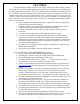
FEATURES The Nomad SD and SD2 Controller have many features that make finding satellites simple and fast. All of the satellite pointing and identification is taken care of by the Nomad SD and SD2 Antenna and Controller. After your controller has been installed and configured, push the “POWER” ON button followed by the “FIND” button (to put your antenna into “search” for satellites mode) and your system will do all the work.
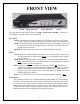
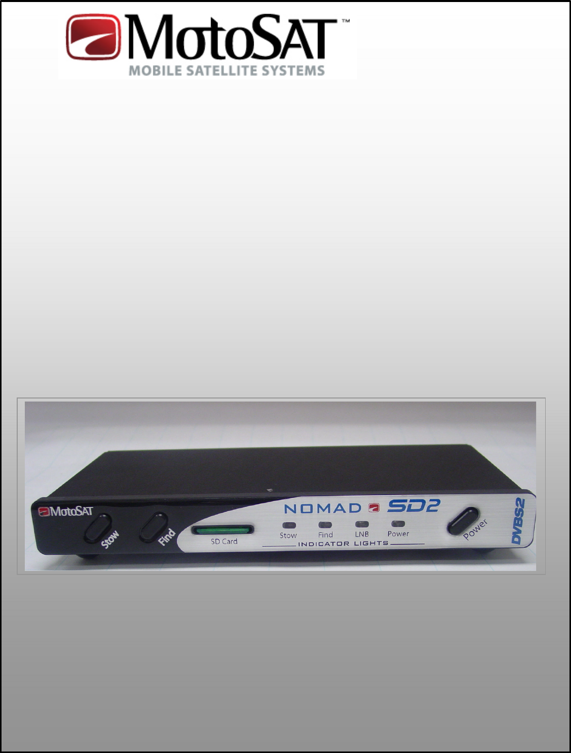
FRONT VIEW STOW FIND SD Card Status Indicators Power The Front Panel consists of three buttons; “STOW”, “FIND” and “POWER.” It also has 4 LED indicators; STOW, FIND, LNB and POWER. BUTTONS STOW: This button will return the dish to the “STOWED” position for travel. It also works in conjunction with the FIND button to put the unit into “Test Dish Mode.” FIND: This button will start the Nomad SD/SD2 searching for satellite(s).
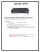
REAR VIEW 12 VDC Control Cable To Receiver To Mount The Rear Panel consists of a MAIN POWER and CONTROL CABLE connector, TO RECEIVER and TO MOUNT F-Connectors. The Nomad SD Controller differs from the Nomad SD2 in that the SD Memory Card Slot is located in the rear of the unit between the Control Connector (9 pin) and the “To Receiver” F-type connector. CONNECTIONS 12 VDC: Provides +/- 12 volt DC input power for Controller and Mount operation.
OPERATION POWERING UP the Nomad SD /SD2 Controller After making the entire antenna, controller and receiver connections for the Nomad SD/SD2, press the POWER button. The unit will initiate its self test routines which take only take a few seconds to complete. The FIND, STOW, and LNB LED’s will illuminate momentarily during this process. Once the initialization test routine has finished, the front panel LED display will indicate the status of the dish.
STOWING the Dish To stow the dish (place it into the travel position (fully retracted)) press the “STOW” button once and the controller will begin to return the dish to the travel position. The STOW LED will flash while stowing. The “STOW” button can be pressed anytime during the search for and after locking onto a satellite(s). Once the dish is stowed, the controller will shut itself down automatically. SD MEMORY CARDS The system will operate properly with or without a memory card inserted.
LOG FILES Log files are a diagnostic tool for monitoring the system as it goes through its various routines. Data will automatically be copied into the “LOGFILES” folder on the memory card being used if there is a folder marked “LogFiles” on the SD Card. If there is not a LOGFILES folder on the SD memory card, the Nomad SD/SD2 will not capture data. If you want to capture diagnostic data you have to create a “LogFiles” folder. It must be identified as “LogFiles”.
ERROR CODES Indicated by sequential flashing of the “FIND” LED Code Description Critical Error = ! (Factory action required) Probable cause 0 NO ERROR 1 MOTOR, MOVING Normal Operation 2 INVALID MODE 1 Check Configuration 3 INVALID MODE 2 Check Configuration 4 MOTOR, TIMEOUT EL 5 MOTOR, TIMEOUT AZ Check sensors or Wiring 6 MOTOR, TIMEOUT SK 7 LIMIT ERROR, EL 8 LIMIT ERROR, AZ Check for obstructions 9 LIMIT ERROR SK trees, buildings etc.
SETTING SERVICE AND MOUNT TYPE Using the Front Panel (With Version 29 Software or greater) This process is only needed to be done only once per installation. It is used to marry the controller to the mount. CAUTION!! Do not confuse this software with any earlier versions. If you have a NomadSD.dat file on your Memory Card Remove it from the Root Directory FIRST.
SETTING SERVICE AND MOUNT TYPE To SET SERVICE TYPE after you are in the programming mode. (Note: Pressing the FIND BUTTON will toggle through SERVICE TYPE.) • The FIND LED indicates the Network ID (or SERVICE TYPE) selected.
SHOW MODE SETTINGS FOR SPECIFIC MOUNT TYPE Using the SD Memory Card Note: This configuration process is limited to Microsoft’s Operating system. Sorry, no Mac’s at this time. To use your computer to configure your Nomad SD/SD2, format the SD card to FAT32 and: 1. Select “START”, “ALL PROGRAMS”, “ACCESSORIES” and “Note Pad” on your computer. 2. Enter the Network Configuration number from the selection below and place it on the first line of the file.
EXPANATION SD Card Root Directory Sample of files located in the root directory NomadSD.dat Sample shows a MotoSAT file folder and a Software file. Since the software file is not in a “folder” then it is considered to be in the “Root Directory”. NOTE: The .hex file contains the operating program of the Nomad SD/SD2 and once read it will be stored into the Nomad SD/SD2 memory. After the Nomad SD2 is first configured, it is not necessary to have the software file in the root directory.
Sample of SD Card with no files in the Root Directory There are no files in the “Root Directory”. There is only a MotoSAT file folder.
MOUNT DEFINITION Motors and Sensors (Azimuth, Elevation) Mounting Plate Elevation Sensor Azimuth Sensor Mount (HD) Skew Motor and Sensor Skew Sensor LNB Arm (HD) When replacing a motor, improper handling can result in this…... Tape the motor gear housing together to prevent separation. Motors returned in this condition will be charged a fee.
SENSORS All Sensors for the television mounts utilize the same sensor. It can be used in the Azimuth, Elevation or Skew motor assemblies. 5 ½ threads Depth into the gearbox assembly is important. The lock nuts are in place to keep the sensor at the proper predetermined depth. A good rule of thumb is 5 ½ threads from the end of the sensor to the first nut. NOTE: 1. The depth of the sensor is common for all television motor assemblies. 2. Use care in handling the sensor.
Effective 23 April 2008 3-YEAR LIMITED WARRANTY FOR NEW SYSTEMS PURCHASED AND INSTALLED THROUGH A CERTIFIED DEALER DETAILS BELOW MotoSAT designs and manufactures high quality equipment and makes every effort to insure that you are getting the most reliable product available. In the event your product should fail please follow the guidelines set below.
WARRANTY EXCLUSIONS AND LIMITATIONS XCLUSIONS AND LIMITATIONS • This warranty extends only to the Original purchaser and is not transferable • This warranty does not cover damage due to accident, misuse, abuse, neglect. • This warranty does not cover damage due to wind, lightning, power surges, fire, flood or any other act of nature.
MotoSAT factory certified dealers/installers may request RMA’s via Email and phone at there discretion with or without troubleshooting assistance understanding they are subject to same terms and conditions below. RMA’s have 3 designation subsets. 1. RA = Repair and Return: The customer sends in the defective part or product and we repair it in house and return it to them.
fees. Will you agree to these terms?” [Customers willing to agree to the terms will also receive the following script:] “To help avoid further charges and shipping costs, please ensure the RMA number I will provide you with is clearly marked on the outside of the package”. [Customers unwilling to agree to theses terms will be directed to follow the RA designation.] MISREPRESENTATIONS • MotoSAT has not authorized anyone to make representations or warranties other than the warranties contained herein.
Notes Date of Purchase________________ DD / MM / YY Installing Dealer __________________________________ Telephone Number ______/_____/_________ System Model Number ________________________ Serial Numbers ____________ ________________ Repairs ________________________________________ _________________________________________ _________________________________________ _________________________________________ Version of Software Date ___________ Rev. No. ________ Date ___________ Rev. No.
For additional information at this time contact MotoSAT Technical Support @ 800-247-7486 The MotoSAT Technician will ask you 1. What is your of Mount “Type” (Skewable or Non-Skewable) 2. What “Service” do you subscribe to 3. If you feel that it is a Warranty problem then be sure that you have your system registered before you call else it will be treated as a nonwarranty situation. Thank you for your assistance, Your Friends at MotoSAT MotoSAT 1955 South Milestone Dr.