
User's Guide
T01150 - Wireless ECF User Guide.doc
(c)2009 Tensator Ltd Page 3 of 10
2 Hardware Configuration
A data connection to the CTRX (transceiver) and the Tensator hub is provided using USB. The unit
comes with an A to B USB cable which is connected from the connector on the base of the CTRX and the
Tensator hub. The CTRX will show as a serial port on the hub.
There are no zone switches on either the CTRX nor the RF buttons. This is now controlled by software.
2.1 PDUs
The PDUs show their serial number and the zone and address settings from switch-on. The serial is
used to program the zone and address for each individual unit.
Power is provided for by a two pin terminal on the reverse of the PDU electronic board. A 5V power
supply is provided. The PSU comes with UK, EU and US mains adaptors. Mains is required due to the
high current usage of the unit. The PDUs can also be powered if connected to a PDU Interface unit. In
this case the power is supplied via the CAT5 cabling.
2.2 Buttons
The button units are programmed by holding down both buttons on the unit until the left LED goes amber
then releasing the buttons. This writes the buttons serial number into the configuration system on the
hub. The address is then set using the configuration system and the two RF buttons must be held down
again in the same way as before. This is covered in more detail in the software section.
Power is provided using a 9V PP3 battery. This gives a true wireless solution for the RF buttons.
Each button unit has two LEDs. LED 1 is on the top left, LED 2 is on the top right.
LED 1 Functions LED 2 Functions
Red – waiting reply reserved for future use
Green – got reply
Amber – ready to send serial
Red flashing for time – low battery
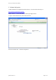
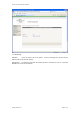
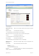
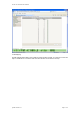
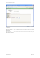
Software Configuration