
User Manual


Page 10 RF Technology R220
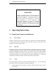
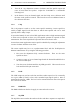
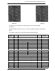
2 RECEIVER INTERNAL JUMPER OPTIONS
RX PCB TX PCB
The Receiver and Transmitter modules plug into the back plane DB25/F
connectors
Miniature spade connectors (2.1 x 0.6 x 7mm) are captive/ soldered at the labelled
points.
To configure: Solder wire connections between appropriate points
.
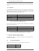
Receiver
DB25/F
RX
PCB
DESCRIPTION
TX
PCB
Transmitter
DB25/F
1, 14 +12V +12V DC SUPPLY +12V 1, 14
2 TXD TX Data TXD 2
15 RXD RX Data RXD 15
3 COR+ Carrier Operate Sw+ PressToTalk input PTT 3
16 COR- Carrier Operate Sw- Tx/Rx output T/R 16
4 TONE Subtone output Hi Z audio input+ AUD+ 4
17 AUDIO Audio output Hi Z audio input- AUD- 17
5 AGND Audio Ground Ext tone input+ TONE+ 5
18 DISC Discriminator output Ext tone input- TONE- 18
6 LINE+ Line output+ Line input+ LINE+ 6
20 LINE- Line output- Line input- LINE- 20
8 EXT SQ Ext Squelch input Auto Level Control ALC 8
13, 25 GND Ground, 0V GND 13, 25
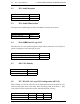
21 BCD 1 Channel select 1’s digit BCD 1 21
9 BCD 2 Channel select 1’s digit BCD 2 9
22 BCD 4 Channel select 1’s digit BCD 4 22
10 BCD 8 Channel select 1’s digit BCD 8 10
23 BCD 10 Channel select 10’s digit BCD 10 23
11 BCD 20 Channel select 10’s digit BCD 20 11
24 BCD 40 Channel select 10’s digit BCD 40 24
12 BCD 80 Channel select 10’s digit BCD 80 12