
User Manual

Page 6 RF Technology R220
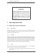
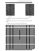
1.1 Front Panel Controls and Indicators
1.1 OPERATING INSTRUCTIONS
2.
Turn the N. SQ. adjustment counter clockwise until the squelch opens and
noise is heard from the speaker. Adjust the VOLUME to a comfortable
listening level.
3. In the absence of any on channel signal, turn the N.SQ. screw clockwise until
the noise in the speaker is muted. Then turn the screw two additional turns in
the clockwise direction.
1.1.4 C.SQ
The C.SQ trimpot is used to set the carrier squelch sensitivity. Carrier squelch is
useful at higher signal levels than those at which noise squelch and can be used
typically from 1-200
µ
V input.
It is provided mainly for use in fixed link applications where a high minimum signal
to noise ratio is required or where very fast squelch operation is required for data
transmission. The carrier squelch will open and close in less than 2 mSec.
In most base station applications carrier squelch is disabled by turning the adjustment
counter clockwise until the screw clicks.
The carrier squelch may be set to a predetermined level with the Techelp/Service
Monitor 2000 software or by using the following procedure:
1. First turn the adjustment fully counter-clockwise. Then set the noise
squelch as above.
2. Connect a source of an on channel signal with the desired threshold level to
the receiver's RF input.
3. Turn the screw clockwise until the SQ LED goes OFF. Then turn the screw
back until the LED just comes ON.
1.1.5 LINE
The LINE trimpot is used to set the line and direct audio output level. It is normally
set to give 0dBm (775mV) to line with a standard input signal equal to 60% of
maximum deviation at 1 KHz. The level can be measured between test socket pins 6
and 1 and set as desired.
1.1.6 PWR LED
The PWR LED shows that the dc supply is connected to the receiver.
1.1.7 SQ LED
The SQ LED comes on when the audio to the line and direct outputs is un-squelched.