
User Manual

RF Technology R220 Page 7
2 RECEIVER INTERNAL JUMPER OPTIONS
The LED and squelch function are controlled by noise, carrier and tone squelch
circuits.
1.1.8
ALARM LED
The ALARM LED can indicate the detection of several different fault conditions by
the self test circuits. The alarm indicator shows the highest priority fault present.
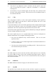
Receivers using software issue 5 and higher use the cadence of the LED flash
sequence to indicate the alarm condition. Refer to table 1.
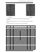
LED Flash Cadence Fault Condition
5 flashes, pause Synthesizer unlocked
4 flashes, pause Tuning voltage outside limits
3 flashes, pause Signal level below preset threshold (fixed link)
1 flash, pause dc supply voltage low or high
LED ON continuously External squelch is active
Table 1: Interpretations of LED flash cadence
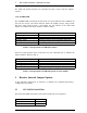
Receivers using software issue 4 and lower use the LED flash rate to indicate the
alarm condition. Refer to table 2.
Indication Fault condition
Flashing, 8 per second Synthesizer unlocked
Flashing, 4 per second Tuning voltage outside 2-7 Vdc
Flashing, 2 per second Signal level below preset threshold (fixed links)
Continuous dc supply voltage low or high
Table 2: Interpretations of LED flash speed, for early models.
2 Receiver Internal Jumper Options
In the following subsections an asterisk (*) signifies the standard (Ex-Factory)
configuration of a jumper.
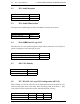
2.1 JP1: 240 Hz Notch Filter
JP1 allows the 240Hz notch filter in the normal audio path to be bypassed.
Condition Position
Notch Filter In 1-2 *
Notch Filter Out 2-3