
User Manual


Page 8 RF Technology R220
2.2 JP2: Audio Response
2 RECEIVER INTERNAL JUMPER OPTIONS
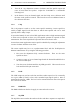
2.2 JP2: Audio Response
Condition Position
750 uSec. de-emphasis 1-2 *
Flat response 2-3
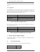
2.3 JP3: Audio Filter In/Out
JP3 bypasses the 300Hz high-pass filter and 240Hz notch filter if necessary.
Condition Position
Hi-pass, Notch In 2-3 *
Flat response 1-2
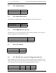
2.4 JP4: 600
Ω
ΩΩ
Ω
Line dc Loop COS
JP4 allows the dc return path through the output audio transformer to be broken, to
permit dc signaling via the audio pair or wires.
Condition Position
dc Loop Configured by JP7, JP8, JP9 1-2 *
dc Loop Not used 2-3
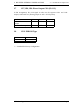
2.5 JP6: COS Polarity
Condition Position
Active on Signal 2-3 *
Active on No Signal 1-2
2.6 JP7, JP8, JP9: dc Loop COS Configuration (JP4 1-2)
These settings are relevant when the Carrier Operated Switch (COS) signal is to be
used across the same wires as the audio. Refer to setting of JP4, in section 2.4. They
control the levels and connection into the audio balanced line circuitry.
Condition JP7 JP8 JP9
Source +12 Vdc Loop 2-3 ON 1-2 *
Free Switch Output 1-2 ON 2-3