
User's Manual

ECLIPSE2 IPCommander User Manual
22
6. Signals
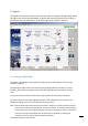
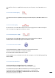
The Signals menu panel provides a visual tool with which to configure the Signal Map. Within
the signal map, various Function Blocks are placed and interconnected to set the required
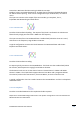
base station controls and features. An example signal map is shown in Figure 12.
Figure 12 Signals Panel
6.1. Using the Signal Map
The Signal map configures the Eclipse2 by using various function blocks to form a base
station or repeater.
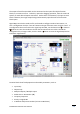
Configuring the signal map is carried out by using a drag and drop interface. To insert a
function, select an item using the mouse from the right side panel and drag it onto the
map.
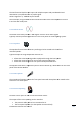
To remove a function block from the map, right click the item and select “Remove”.
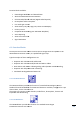
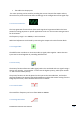
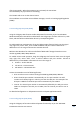
To connect the function blocks together click the small red square in the centre of one
function and drag a line to the next function down the chain.
Note: Function Blocks have directional inputs and outputs. Outputs can only be connected to inputs.
Some functions, like the FM Demodulator, have only an output. For example when drawing a
connecting line start at the FM Demodulator and drag it to the Tone Decoder, not the reverse.
If the Error message “Target Block does not have Input” is displayed, try drawing the
connection line in the reverse direction between the blocks.