
Operating instructions


RF Technology R70/R71 and R150 Page 15
5.11 Voltage Regulator 5 CIRCUIT DESCRIPTION
5.11 Voltage Regulator
The dc input voltage is regulated down to 9.4 Vdc by a discrete regulator circuit. The
series pass transistor Q20 is driven by error amplifiers Q21 and Q22. Q23 is used to
start up the regulator and once the circuit turns on, it plays no further part in the
operation.
This circuit is short circuit and overload protected. It provides much better line
isolation and lower dropout voltage than can be obtained with current integrated
circuit regulators.
6 Alignment Procedure
The following procedures may be used to align the receiver for optimum
performance. Normally only RF alignment will be required when changing
frequencies. IF alignment should only be necessary after repairs on that part of the
circuit.
Reference oscillator or TCXO calibration may be required periodically due to crystal
aging. The aging should be less than 1 ppm/year.
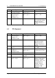
6.1 Standard Input Signal
RF Signal Generator
50Ω output impedance
Frequency range 66 - 174 MHz
FM modulation at 1KHz
1.5KHz peak for 12.5KHz channel spacing
3.0KHz peak for 25KHz channel spacing.
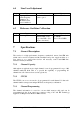
6.2 RF Alignment
Alignment Frequency
66-84 MHz range 76.000 MHz
70-88 MHz range 80.000 MHz
136-156 MHz range 146.000 MHz
148-168 MHz range 158.000 MHz
154-174 MHz range 164.000 MHz