
Operating instructions


Page 16 RF Technology R350/R500
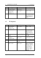
6 ALIGNMENT PROCEDURE 6.3 IF Alignment
Step Input Measure Adjust
1 Select alignment
frequency channel
dc Volts on test socket
pin 9 to pin 1
L34 to read 4.00Vdc
2 Signal generator on
centre frequency
channel to J1.
Modulation off.
dc Volts on test socket
pin 7 to pin 1
Generator level to
read 1 - 2 Vdc
3 As Above As Above L29, L31, L36, L38
for maximum reading.
Reduce generator
output to keep below
2 Vdc
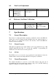
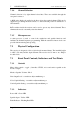
6.3 IF Alignment
Step Input Measure Adjust
1 Signal generator on
center frequency
channel to J1.
Modulation OFF
dc Volts in test socket
pin 7 to pin 1
Generator level to
read 1 - 2 Vdc
2 As Above As Above L5, L6, L7, L8 for
maximum reading.
Reduce generator
output to keep below
2 Vdc
3 Set generator level to
10 µV
Frequency U3 pin 9 L9 to read 455 KHz
+/- 10Hz
4 Set generator level to
1 millivolt.
Modulation ON.
Audio level test socket
pin 6 to pin 1
Line level (RV3) to
obtain approx.1Vrms
5 As Above As Above L10 for maximum
6 As Above Audio level P1 pin 18
to pin 5
RV1 for 0.5 Vrms
7 Set generator level to
approx. 25µV
SINAD on test socket
pin 6 to pin 1
Reduce generator
level to obtain 12 Db
SINAD. Carefully
adjust L5, L6, L7, L8
to obtain the best
SINAD. Reduce
generator output to
maintain 12 dB
SINAD