
Operating instructions


RF Technology T350/T500 Page 6
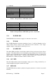
1.1.3 PWR LED 1 OPERATING INSTRUCTIONS
LED Flash Cadence Fault Condition
5 flashes, pause Synthesizer unlocked
4 flashes, pause Tuning voltage out of range
3 flashes, pause Low forward power
2 flashes, pause High reverse (reflected) power
1 flash, pause Low dc supply voltage
LED ON continuously Transmitter timed out
Table 1: Interpretations of LED flash cadence
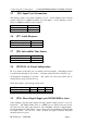
Indication Fault Condition
Flashing, 8 per second Synthesizer unlocked
Flashing, 4 per second Tuning voltage outside correct range
Flashing, 2 per second Low forward power
Flashing, 1 per second High reverse power
Continuous dc supply voltage low or high
Table 2: Interpretations of LED flash speed, for early models
1.1.3 POWER LED
The PWR LED shows that the dc supply is connected to the receiver.
1.1.4 TX LED
The TX LED illuminates when the transmitter is keyed. It will not illuminate (and an
Alarm cadence will be shown) if the synthesizer becomes unlocked, or the output
amplifier supply is interrupted by the microprocessor.
1.1.5 ALARM LED
The Alarm LED can indicate several fault conditions if they are detected by the self test
program. The alarm indicator shows the highest priority fault present. Receivers using
software issue 5 and higher use the cadence of the LED flash sequence to indicate the
alarm condition. Refer to table 1. Receivers using software issue 4 and lower use the
LED flash rate to indicate the alarm condition. Refer to table 2.
1.1.6 ALC LED
The ALC LED indicates that the transmitter output power is being controlled by an
external amplifier through the external ALC input
1.1.7 REF LED
The REF LED indicates that the synthesiser frequency reference is locked to an external
reference.