
Operating instructions


___________________________________________________________________________
RF Technology R800 Page 14
6.3 IF Alignment 6 ALIGNMENT PROCEDURE
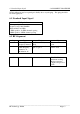
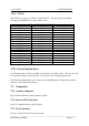
6.3 IF Alignment
Step Input Measure Adjust
1 Signal generator on
centre frequency
channel to J1.
Modulation OFF.
dc Volts on test
socket pin 7 to pin
1
Generator level to
read 2-3Vdc.
2 As above As above L5,L6,L7,L8 For
max. Reduce
generator output to
keep below 3Vdc
3 Set generator level
to 10uV
Frequency U3 pin 9
L9 to read 455KHz
+/- 10Hz
4 Set generator level
to 1 millivolt.
Modulation ON
Audio level test
socket pin 6 to pin
1
Line level (RV3) to
obtain approx.
1Vrms
5 As Above As Above L10 for maximum
6 As above Audio level P1 pin
18 to pin 5
RV1 for .5Vrms
7 Set generator level
to approx 0.25uV
SINAD on test
socket pin 6 to pin
1
Reduce generator
level to obtain
12dB SINAD.
Carefully adjust
L5,L6,L7,L8 to
obtain the best
SINAD. Reduce
the generator
output to maintain
12dB SINAD.
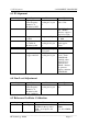
6.4 Line Level Adjustment
Step Input Measure Adjust
1 Signal generator on
centre frequency
channel to J1.
Modulation ON.
Level 1 millivolt
Audio level test
socket pin 6 to pin
1
RV3 for 775mV
rms
6.5 Reference Oscillator Calibration
Step Input Measure Calibration
1 None required Frequency Junction of R69
and R26 on the top of the
PCB. (L.O. input to the
mixer)
X01 for L.O. +/-
100Hz
L.O. =Fc+45MHz