
Operating instructions


___________________________________________________________________________
RF Technology R800 Page 8
3 RECEIVER CONNECTIONS 3.1.25 Pin Connector
3 Receiver I/O Connections
3.1 25 Pin Connector
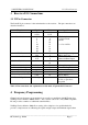
The D-shell 25 pin connector is the main interface to the receiver. The pin connections are
described in table 3.
Function Signal Pins Specification
DC Power +12Vdc
0 Vdc
1,14
13,25
+11.4 to 16Vdc
Channel select 1
2
4
8
10
20
40
80
21
9
22
10
23
11
24
12
BCD Coded
0 = Open Circuit
or 0 Vdc
1 = +5 to +16Vdc
RS232 Data In
Out
15
2
Test and Programming use
9600, 8 data 2 stop
600 Ohm Line High
Low
20
6
Transformer Isolated
Balanced 0 dBm Output
150 Ohm/Hybrid Access 7
19
Discriminator Audio Disc 18 AC coupled, unsquelched
Direct Audio Output Audio 17 Direct AC Coupled Audio
Audio Ground Agnd 5 Direct Audio Ground
Sub-Audible Audio Output Tone 4 Unsquelched, 1-250 Hz
Carrier Operated Switch COS+
COS-
3
16
Opto-coupled Transistor
Switch (10mA)
External Squelch Ext Sq 8 <1 Vdc to Squelch
>2 Vdc or open ckt to
unsquelch
Table 3: Pin connections and explanations for the main, 25-pin D-shell Connector
4 Frequency Programming
Channel and tone frequency programming is most easily accomplished with RF Technology
TecHelp/ Service Monitor 2000 Software. This software can be run on any IBM compatible
PC and provides a number of additional useful facilities.
TecHelp/ Service Monitor 2000 allows setting of the adaptive noise squelch threshold,
provides a simple means of calibrating the signal strength output and minimum signal alarm