
Operating instructions

RF Technology PA501 Page 10
4.1 Description 4 SPECIFICATIONS
1. Set the unit up on a bench with the test equipment as given in table 3
2. Disable the ALC loop
3. Connect the output of the 15 Watt source directly to the annenuator, bypassing the
PA501 amplifier.
4. If you are using a network analyser, carry out calibration according to the
instruments instructions so as to obtain a 0 dB display from about 425MHz to
525MHz. Set the sweep time to no less than 0.2s, and the stimulus power to +42
dBm (15W). If you are using a swept source etc., store the response of the test
arrangement into a reference memory of the ’scope.
5. Connect the PA501 back in the circuit, and apply power.
6. The amplifier should have a gain of 10 dB across the frequency band, the collector
currents of Q1/Q2 should be within 20% of each other, and less than 10A each, at
each frequency in the sweep. The power delivered should exceed 125W across the
whole band.
7. Adjust the variable capacitors to achieve the above conditions. Beware achieving
higher gain across a narrow band. Also note that performance will change a little
when the lid is bolted down.
8. Reconnect the ALC loop. Check that the power levelling is working to within a dB
using a sweep speed of about 20MHz/second.
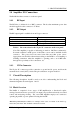
Power Supply 13.8V dc (<25A)
RF Source
15 Watt swept source, 450-512MHz e.g., Network Analyser,
Spectrum Analyser and tracking generator, or sweep
generator and RF amplifier
RF Load
Attenuator, 50Ω, 150W, SWR<1.2:1
RF Power Meter
e.g. Network Analyser, Spectrum Analyser, or HP532D
calibrated detector and digital storage scope
Dc Power Monitor Q1/Q2 collector current
Table 3: Swept-frequency test equipment and conditions for the PA501
Power Amplifier.
4 Specifications
4.1 Description
The PA501 power amplifier is designed for use with the T500 series transmitters to
provide 120 Watts of RF output. Output power is regulated by connecting the ALC
output to the ALC input of the T500. The drive from the transmitter module is then
automatically adjusted to maintain the required output.