
Operating instructions


RF Technology R50 Page 3
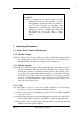
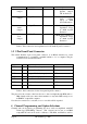
is out of range.
1 flash, pause Low dc supply voltage
LED ON continuously External squelch is active
Table 1: Interpretations of LED flash cadence
2 Receiver Options
There are many software selectable options. Some options are selected on a per
channel basis, and some are defined globally (i.e. the parameter is fixed
irrespective of which channel is selected). Below is a description of these
global parameters
2.1 Serial I/O Parameters
There are two serial ports. There is the main serial port which is brought out to the
front panel connector. This is referred to as PORT0. There is another serial
port which is for factory use only. It is referred to as PORT1.
The baud rate, can be defined for PORT0. PORT0 is set by default to 57.6Kbps, with
No parity.
2.2 Receiver Low Battery Level
This is factory set to 24.0V, and defines the level of the DC supply that will cause a
Receiver dc supply low alarm.
2.3 LOOP Volts Select
By default, when the squelch opens and the Line output audio is enabled, 12V is
applied to the
Line+/Line- pair through 680 ohms. The 12V power source is
removed when the squelch closes.
In Rev. 2 receivers, the user can select to reverse the application of 12V,
ie 12V
is
applied when the squelch is closed, and removed when the squelch opens.
In Rev. 3 (or later) receivers, the user can select to apply a DC loop to the
Line+/Line-
pair instead of applying 12V. Similarly, they can select to reverse the
application of the Loop, or the voltage, depending on the squelch state.
2.4 COS Source/Sink Select
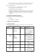
The COS output can have four possible states:
a)
12V: 12V is applied to COS+/COS- through 680 ohms,
b) 0V: ie COS+ is shorted to COS- which is shorted to GND,
c)
shorted: COS+ and COS- are shorted together, but both are electrically
isolated,
d)
open: COS+ and
COS- are not shorted together, but both are electrically
isolated
In states (a) and (b), the receiver applies either 12V to the COS+ pin, or GND. The
COS- pin is connected to GND in both states. The receiver acts as a “source”
when in either of these two states.