Eclipse Ser ies RF Technology Pty Ltd rfinfo@rftechnology.com.
CONTENTS CONTENTS Contents 1. Installing WinTekHelp On Your Computer 5 2. Setting Up 5 3. Main Menu 8 3.1 View Operational Data 3.1.1 Exciter 8 3.1.1.1 Current Channel 8 3.1.1.2 Battery Level 9 3.1.1.3 Ref Volts 9 3.1.1.4 Firm Rev 9 3.1.1.5 Model 9 3.1.1.6 Serial No. 9 3.1.1.7 Control Input Status 9 3.1.1.8 RF Output (Exciter) 9 3.1.1.9 Audio Line and Tone Status 10 3.1.1.10 Reference Oscillators and VCOs 11 3.1.1.11 PA Status 12 3.1.1.12 ALARM Status 12 3.
CONTENTS CONTENTS 3.2.1.2 Frequency 20 3.2.1.3 CTCSS Tone or DCS Code 20 3.2.1.4 No Tone Period 21 3.2.1.5 Tx Tail 21 3.2.1.6 Maximum Deviation 21 3.2.1.7 Tone Deviation 22 3.2.1.8 High Gain 22 3.2.1.9 Line Input 22 3.2.2 Advanced Programming for the Exciter 3.2.2.1 Channel No 22 3.2.2.2 Both/Primary/Alternate 22 3.2.2.3 Frequency 22 3.2.2.4 CTCSS Tone or DCS Code 22 3.2.2.5 Tx Start Delay 23 3.2.2.6 No Toner Period 23 3.2.2.7 Tx Tail 23 3.2.2.
CONTENTS CONTENTS 3.3.2 Parameter Programming for the Receiver 31 3.4 Other 33 3.5 Exit to Windows 34 3.6 Go To Prompt Window 34 3.6.1 Master Menu 34 3.6.2 File 34 3.6.3 Baud Rate 35 3.6.4 Channel Programming 35 3.6.5 Parameters 35 3.6.6 Operational Data 35 3.6.
WinTekHelp User Manual Installing WinTekHelp On Your Computer WinTekHelp User Manual 1 Installing WinTekHelp on your computer You must have an IBM compatible Personal Computer (PC) running Windows95 Release 2 or higher. The recommended screen resolution of your PC is 800 X 600 pixels, or higher. Your PC will need a CD player, or be connected via a network to another Personal Computer which can read Compact Discs to enable WinTekHelp to be installed.
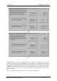
2. Setting Up WinTekHelp User Manual Fig 1 Fig 2 Run WinTekHelp (See Section 1). WinTekHelp defaults to a serial baud rate of 57600 bits per second, with no parity, and to the serial port chosen in the installation procedure (See Section 1). Each Receiver and Exciter is factory configured to run at 57600 bps and with no parity. WinTekHelp, from version 1.
WinTekHelp User Manual 2. Setting Up Fig 3 Fig 4 If you have a problem with the cable, fix the problem, and click on the RETRY button. If you are not able to use the default COMM port (eg it is being used by a mouse or an internal modem), then you will need to Cancel (by clicking on the little button marked “X” on the top right of the dialog box) and try running WinTekHelp again. You may wish to prepare program files for an exciter or a receiver when no device is attached to your PC.
3. Main Menu WinTekHelp User Manual Clicking on the Button marked “Edit Channel Data Files?” will give you a new dialog box. Fig 11 shows this dialog box. See Section 3.2 for details on how to examine or modify channel data files. Clicking on the Button marked “Edit Parameter Data Files?” will give you a new dialog box. Fig 17 shows this dialog box. See Section 3.3 for details on how to examine or modify parameter data files.
WinTekHelp User Manual 3.1.1.2 Battery Level If both the MSN and the LSN have values below 9, then they define the channel number as a two-digit BCD number, with values from 00 to 99. For example, jumpers on “80”, ”10”, “02”, and, “01” defines channel 93. If the MSN is greater than 9, then the channel number is derived from the formula 16*MSN + LSN where the LSN and the MSN are now hexadecimal numbers.
3.1.1.9 Audio Line and Tone Status WinTekHelp User Manual The RF pre-amplifier is a two-stage bipolar transistor amplifier. The first stage has a DC bias applied to it, when the exciter is keyed up, which controls the overall gain of the amplifier. This bias is manipulated by the firmware in the exciter to regulate the power output from the external power amplifier. The bias voltage, though, is controlled through two sources. There is a coarse control, which is used to select one of three control bands.
WinTekHelp User Manual 3.1.1.10 Reference Oscillators & VCO’s The gain, that is defined by the Line Potentiometer and the firmware, is applied to the Voltage Controlled Amplifiers (VCAs) on Line 1, Line 2, and the Tone Deviation (digital) Pot if the External Tone Input is enabled. The current settings of the two VCAs are shown in the fields referred to as “Line 1 VCA Adjustment” and Line 2 VCA Adjustment”. This shows the gain setting as a percentage of full scale.
3.1.1.11 PA Status .3.1.1.11 WinTekHelp User Manual PA Status There are twelve fields in this section, which describe the state of the external Power Amplifier. If there is no RF Technology’s Eclipse50 series power amplifiers connected to the exciter, these fields will be blank. The Eclipse series Power Amplifiers have their own A/D converter on-board, and the exciter interrogates the data from this A/D converter via a 3-wire digital bus.
WinTekHelp User Manual Fig 5 Fig 6 One PLL is referred to as the Modulation PLL. That is because the modulation signal is applied to this PLL, but not the other. The other PLL is called the Channel PLL. This latter PLL is the one that changes frequency, dramatically when the selected frequency changes. The Modulation PLL may change by up to +/- 250kHz, when the Channel changes.
WinTekHelp User Manual “Battery Low” is generated if the exciter battery level is low. “RF Output Stage Failure” is asserted if, for some reason, bias is applied to the Exciter’s pre-amplifier, and there is less than 20mW output power. “PLL Tuning Volts Not OK” is asserted if either, or both, of the bias voltages in the two VCO circuits is out of range. “Channel Not Programmed” is asserted if there is no channel data associated with the current channel number.
WinTekHelp User Manual 3.1.2 3.1.2 Receiver Receiver To understand some of the sub-sections of this Section it may be necessary to review the Block Diagram of the receiver shown in Fig 23, in Appendix A. .3.1.2.1 Current Channel This displays the current channel. The current channel is a number from 0 to 255, which is used to select which frequencies or tones etc, the receiver tunes to or scans when the receiver powers up. .3.1.2.2 Battery Level This is the voltage supplied to the receiver.
WinTekHelp User Manual The mechanism by which the receiver determines the Current Channel is the same as for the Exciter. [See Section 3.1.1.
WinTekHelp User Manual 3.1.2.7 Received Frequency and Tone The dc voltage across the front panel N.Sq potentiometer is read and then converted to an approximateSINAD1 value, and this approximate SINAD value is displayed in the Noise Squelch Level field. The receiver has a noise blanker circuit that can be disabled. If the circuit is enabled the button referred to as “Noise Blanker On/Off” will be “ticked”.
3.1.3.9 Audio State .3.1.2.9 WinTekHelp User Manual Audio State The “De-Emphasis or Flat freq. Response” field displays if the de-emphasis circuit has been switched in or not. This field will display “DE-EMPHASIS” or “FLAT”. The Input Peak Deviation field displays the level of the unfiltered received audio in terms of peak deviation. After calibration, this value should be accurate to about 5% when the received signal strength is greater than -110dBm and the deviation is at least 3kHz.
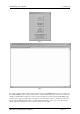
WinTekHelp User Manual 3.2 Edit/Examine Channel Data Fig. 10 3.2 Edit/Examine Channel Data Click on this button in the Main Menu to examine and/or modify the channel data for the receiver or exciter. After clicking on this button, WinTekHelp will upload the existing channel data from the receiver or exciter. Whilst this occurs a Progress bar is displayed. When that is complete, a dialogue box as shown in Fig 11 will open.
3.2.1 Standard Channel Programming for the Exciter WinTekHelp User Manual can be written to the receiver’s or exciters Flash memory, or it can be written to a file, or it can be appended to an existing file. These three options are selected from the bottom three buttons of the dialog box shown in Fig 13. Note that “program” files can have both parameter and channel data in them. If one edits channel data, it can be appended to an existing parameter program file by using the Append option.
WinTekHelp User Manual 3.2.1.4 No Tone Period frequency of the last IF stage before the discriminator. To “invert” a code before transmission, click on the checkbox marked “Invert”. .3.2.1.4 No Tone Period Generally, at the end of transmission, an exciter will remove the tone from being generated before the transmission is stopped.
3.2.1.7 Tone Deviation .3.2.1.7 WinTekHelp User Manual Tone Deviation Different tone panels and systems prefer CTCSS tones and DCS codes to be generated with different deviations. One can select the tone deviation to use by clicking on the button, with the upside down triangle, which is to the right of this field. This opens a menu of available tone deviations, from which the user can select one. The actual tone deviation is set up at calibration to be a percentage of maximum deviation.
WinTekHelp User Manual 3.2.2.5 Tx Start Delay By clicking at the top or the bottom of the “Spin button” to the right of this field, one can step up or down to the next “standard” RS470 tone. The field will display the tone value selected (in Hertz) and its EIA code. As well as CTCSS tones, from Rev 4 hardware, DCS codes can also be sent. These can be entered in the conventional way as 3 digit octal codes.
3.2.2.10 High Gain WinTekHelp User Manual Fig 13 .3.2.2.10 High Gain If the applied audio input signal is at a lower level than the usual 0dBm level, the user can switch in a 20dB-gain pad in the audio circuit. By clicking on this button, this extra gain pad will switch-in when this channel is selected and the exciter keys up. (Note that this has no effect if the microphone PTT is keyed). .3.2.2.11 Line Input There are two transformer coupled audio Inputs, Line1, and Line 2.
WinTekHelp User Manual 3.2.3.2 Frequency Each channel can have a unique set of parameters. Thus, a receiver can have 256 different operating states, depending upon the channel number read from the rear panel, or, what channel select override parameter has been programmed. The user can directly enter the channel number, or click at the top or bottom of the “Spin Button” to the right of this field to step up or down through the list of channels.
Advanced Programming for Receiver WinTekHelp User Manual By clicking at the top or the bottom of the “Spin button” to the right of this field, one can step up or down to the next RS470 “standard” tone. The field will display the tone value selected (in Hertz) and its EIA code. If the DCS Enable button is selected first, the user can enter the three digit octal DCS code that they wish to have present before opening the Squelch. Note that the code entered is assumed to be not inverted.
WinTekHelp User Manual Fig 15 Fig 16 Depending on the position of the focus, clicking on the left button of the mouse, or the right button, or hitting the INSERT key, or hitting the DELETE key may have some effect. If pressing the key would have an effect, what effect it would have, is described in this area at the bottom of the dialog. Below is a description of the fields and their values in this tree structure.
3.2.4.1 Frequencies .3.2.4.1 WinTekHelp User Manual Frequencies This is a top-level tree item. Under it, are all the frequencies that are allowed in a slot. .3.2.4.2 Delays This is a top-level tree item. Under it are all the COS Start/End and Loop Start/End delays. These Start delays will hold up the generation of COS and Loop for the specified time after detection of a frequency to tune to. This can be used as an “anti-chatter” feature.
WinTekHelp User Manual 3.2.4.7 DCS Code Fig 17 .3.2.4.7 DCS Code Eclipse50 series receivers from Rev. 2 hardware support DCS. If this field exists, it is a third-level tree item. It has only one sub item being the DCS code itself (represented as a 3 digit octal code). .3.2.4.8 COS/LOOP Control This can be a third level or a fifth level item.
3.3.1 Parameter Programming for the Exciter WinTek Help User Manual Note that “program” files can have both parameter and channel data in them. If one edits the parameter data, it can be appended to an existing channel data program file by using the Append option. Note also that when data is written to the flash database of the exciter or receiver, all the channel and parameter data has to be erased, and then rewritten.
WinTekHelp User Manual 3.3.2 Paramater Programming for the Receiver The level, at which Low Battery Alarms are generated, can be defined in the box called, “Exciter Low Battery Alarm level”. The exciter will normally key up because PTT or LOOP, etc are asserted, and transmit forever. If the value in the “Max Transmit Time” Box is non-zero, then the exciter will key off after the defined time, and generate a Transmit Timeout Alarm. The time can be entered in hours, minutes, and seconds.
3.3.2 Parameter Programming for the Receiver WinTekHelp User Manual Fig. 19 The COS output can have four states: 1. Open Circuit: COS+ and COS- are isolated from ground and from each other. Dc current cannot flow from COS+ to COS-, nor from either leg to ground. If this is the Default State, the asserted state is “Looped”. 2. Looped: dc current will flow from COS+ to COS- through an opto-coupler. COS+ and COS- are isolated from ground.
WinTekHelp User Manual • 3.4 Other will give more priority (in terms of frequencies looked at) to the original frequency; it will actually test the original frequency every second test. It will only do this, though, for the period defined in this field , which starts from the time when the receiver first switched back to the priority frequency. The default value for this timeout is 25 seconds.
3.5 Exit To Windows WinTekHelp User Manual The middle left button, “Create Master BackUp File”, creates a file in WinTekHelp’s home directory with the name serialno.r50, for a receiver, or serialno.t50 for an exciter, where “serialno” is the actual serial number of the receiver or exciter. This file contains all the parameters, and channels, for that receiver and exciter, and can be used to restore all values to a known good set.
WinTekHelp User Manual 3.6.3 Baud Rate The “Download Firmware” list item will take you to the same place that you would arrive at if you had chosen the ”Other..” button from the Main Menu followed by the “Download new Firmware” button. (See Section 3.5) The “Download Cmd File” list item can be used to download a program file containing both parameters and channel data. It is very similar to choosing the ”Other..
Appendix A Fig 22
Fig 23
Appendix B When using the “spin buttons” to select a CTCSS tone, on the dialogs in Sections 3.3.1 and 3.3.2, WinTekHelp will rotate through the following list of tones shown in Column 1. In the Operational Status dialog shown in 3.1.2, WinTekHelp will show the nearest tone in Column 1 to the received tone, if the received tone is within +/1% of any of these “Standard” tones. Standard CTCSS Tone Frequency in Hertz 67.0 69.3 71.9 74.4 77.0 79.7 82.5 85.4 88.5 91.5 94.8 97.4 100.0 103.5 107.2 110.9 114.8 118.
Appendix C C.1 Exciter s Section 6.2 of the T50 Users Manual describes a procedure to calibrate an Exciter manually. From revision 1.4 of WinTekHelp, this command line method has been given a Windows “front-end”. The underlying calibration program, which is “built into” the firmware is invoked automatically in this Windows front-end, when users choose options from dialog boxes. Consequently the equipment lists etc that are shown in 6.
The second stage, marked as “Reference Clocks”, may be required from time to time depending on how accurate the user wants to keep the exciter’s transmit frequency. The standard exciter comes with 12.0MHz crystals which have a 5ppm accuracy. These crystals will age a few ppm per year. One of these crystals is “locked” to the other with a software based feedback network. In order to calibrate the reference oscillators, the user will need to attach an external reference to the exciter.
The top two horizontal slider displays are used to show how accurate the tracking is. The firmware computes the errors in its two reference clocks every 2 seconds, and the errors found are used to set the arrow marker. The two vertical slider displays are used to show the control values used by the firmware to “track” the frequency. Each vertical slider has two markers. The one on the left shows the value defined by the last calibration and it does not change. The right marker shows the current value.