
User manual

RF Technology WinTekHelp User Manual Page 10
3.1.1.9 Audio Line and Tone Status WinTekHelp User Manual
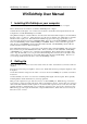
The RF pre-amplifier is a two-stage bipolar transistor amplifier. The first stage has a DC bias applied to
it, when the exciter is keyed up, which controls the overall gain of the amplifier. This bias is manipulated
by the firmware in the exciter to regulate the power output from the external power amplifier. The bias
voltage, though, is controlled through two sources. There is a coarse control, which is used to select one
of three control bands. When the exciter keys up on a new channel, for the first time, it chooses which
control band to use. Upon subsequent attempts to “key up”, the firmware remembers what control range
to use for that channel, and it will automatically select the appropriate one. Which control band is used is
indicated by the button referred to as “Bias State”. If the Low control range is used, then the button will
have no tick. If the Medium control range is used, then the button will have a grey tick, and, if the High
Control range is used, then the tick mark will be black.
The fine control of the bias, which the Exciter uses to control the output power level, is provided from the
output of an 8 bit Digital to Analogue Converter (DAC). The control value for the DAC can vary from 0
to 255. This value is converted to a percentage (of full scale) and displayed in the field referred to as
“Bias”.
.3.1.1.9 Audio Line and Tone Status.
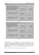
There are fifteen fields in this section, which describe the state of the Audio circuits in the Exciter.
The fields referred to as “Line 1” and “Line 2” display the signal conditioning that may (or may not) be
applied to the two main Audio inputs. The audio input may have Pre-Emphasis applied, or it may have no
signal conditioning, or it may be turned off altogether. These fields show these three states with the
phrases “PreEmphasis”, “Flat”, or “Off”.
Note that if neither Line1 or Line 2 is “Off”, then the audio signals are “mixed”.
The field referred to as “Microphone” shows the status of the Microphone input. If the unit is keyed up
by the microphone, Line 1 and Line 2 will be in the “Off” state and the “Microphone” field will be in the
“On” state.
The External Tone Input can be used as a 3
rd
signal input. It differs from Line 1 and Line 2, in that it is
not transformer isolated. It has a balanced differential input with a CMRR greater than 46dB, and capable
of withstanding a common mode level of over +/- 36V. The input impedances are greater than 10k ohm,
and matched to within 0.5%. This input can be used to modulate the carrier with frequencies from dc to
3kHz, whereas the transformer coupled inputs (Line 1 and Line2) will not pass signals without attenuation
below approximately 50Hz. The External Tone Input can be turned “On” or “Off, and this status is
displayed in the field marked “Extern. Tone Inp.”. Normally, the External Tone Input is “Off”.
The External Tone Input signals are normally passed though a low Pass 300Hz filter before being passed
on to the deviation limiting and then modulation circuits. This low pass filter can be by-passed, thereby
allowing the External Tone Input to be used as a 3
rd
Audio input. The status of this by-pass is shown in
the field referred to as “Tone LPF Bypass”, and it is normally “Off”.
The audio input levels of the Exciter are nominally 0dBm at 600 ohms. With the Line Potentiometer
centred, and a 0dBm signal from a 600 ohm source, the units will transmit a 1kHz signal at 60% of the
maximum deviation level that is set.
If the button marked as “Hi Gain On” is ticked, then the nominal input level is –20dBm on both audio
inputs, in other words, with the Line level Pot centred, a -20dBm input level will generate 60% of
maximum deviation. This field can be programmed on a per channel basis.
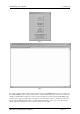
If the Exciter is transmitting a CTCSS tone, then the button referred to as “Tone On” will be ticked, and
the tone frequency itself is displayed in the field referred to as “Tone Freq.”. If the tone is one of the EAI
(RS470) tones, then its alphanumeric code is displayed as well. The current value of Tone Deviation is
displayed in the field referred to as “Tone Dev”. The standard CTCSS tones are listed in Appendix B.
The tone deviation potentiometer is a digital potentiometer and its adjustment value (as a percentage of
full scale) is displayed in the field referred to as “Tone Dev. Pot.”. The tone deviation Potentiometer is
used to set the tone deviation from the CTCSS generator, or, if the external tone input is used, it is used to
set the deviation from that input. If the External Tone input is enabled, adjusting the Line Level Pot up or
down, will change the Tone Dev Pot value that is displayed, up or down. That is because this Tone
deviation Pot is used as a crude control for the External Tone input.
The Line Potentiometer, on the front panel, adjusts a voltage which is “read” by an A/D converter on the
exciter’s microcontroller. The firmware converts the value “read”, to a logarithmic value in the range
+12.3dB(X4) to -12.3dB(÷4). This value is displayed in the field referred to as “Line Level Pot.”. When
the Line Potentiometer is centred, the display should show 0dBm.