
User manual

RF Technology WinTekHelp User Manual Page 13
WinTekHelp User Manual
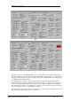
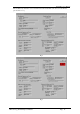
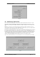
One PLL is referred to as the Modulation PLL. That is because the modulation signal is applied to this
PLL, but not the other. The other PLL is called the Channel PLL. This latter PLL is the one that changes
frequency, dramatically when the selected frequency changes. The Modulation PLL may change by up to
+/- 250kHz, when the Channel changes.
The actual frequency generated by the exciter is the difference between the Modulation PLL and the
Channel PLL frequencies that are displayed in the two fields referred to as “Frequency” in the VCO sub-
section. Note that the Channel PLL frequency will always be a multiple of 20kHz, and the Modulation
PLL will always be a multiple of 31.25kHz. By choosing appropriate frequencies, the difference between
these two frequencies can be set to any multiple of 1250Hz.
The phase detectors generate bias voltages for the VCOs. These bias voltages are between 0.5 and 4.75V
and are displayed in the fields referred to as “VCO Bias”.
Fig 5
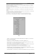
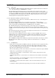
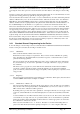
Fig 6