
Technical data


Manual - Gear Units and Gearmotors
219
Index
11
Hygienic design gearmotors 18
I
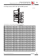
Installation of gear units with hollow shaft and key
Supplied fastening parts
192
Use the SEW installation/removal set 193
International markets 13
L
Lubricants
Anti-friction bearing greases
185
General information 185
Lubricant fill quantities 187
Lubricant table 186
M
Mounting adapter, encoder
120
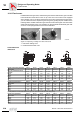
Mounting position designation
Six mounting positions M1-M6
149
Mounting Positions 149
Mounting positions
AC motors
178
Churning losses 45, 155
Helical gearmotors 156
Helical-bevel gearmotors 164
Helical-worm gearmotors 169
Key to the mounting position sheets 155
MOVIMOT® drives 179
Parallel shaft helical gearmotors 161
Spiroplan® gearmotors 175
Mounting system TorqLOC® 195
MOVIMOT® AC motors
Operating modes
131
MOVI-SWITCH®
Theory of operation
138
Multi-stage gearmotors 12, 47
O
Oil compensators
46
Operating modes MOVIMOT® AC motors 131
Order information
Direction of rotation of the output with a backstop
150
Examples 154
Position of output end in right-angle gear units
151
Position of the output shaft and output flange
150
Position terminal box and cable entry 152,
153
, 180
Overhead trolley systems 58
Overhung loads 51
P
Parallel shaft helical gearmotors
Mounting positions
161
Types 32
Plug connectors, contact rating 114
Product description, General 11
Product groups 7
Project planning for AC motors
Cyclic duration factor
95
EMC measures 87
Forced cooling fan 125
Frequency and voltage 90
Motor protection 88
Motors for USA and Canada 92
Overhung load conversion 99
Power reduction 93
Rated data 85
Selecting the tachometer 117
Starting frequency 96
Tolerances 86
with inverter 143
Project planning for drives
Additional documentation
41
Drive selection data 42
Sequence 43
Project planning for gear units
Churning losses
45
Efficiency of SEW gear units 44
Force application, definition 52
Multi-stage gear units 47
Oil compensator 46
Overhead trolley systems 58
Overhung and axial loads 51
Overhung load conversion, gear unit constants
54
Permitted axial load 52
Permitted overhung load 51
RM gear units 55
Self-locking helical-worm or Spiroplan® gear
units
44
Service factor 48
Project planning for RM gear units 55
Project planning of gear units
Off-center force application, overhung load con-
version
53
Project planning sequence 43
Proximity sensor 121
R
RM Gearmotors
12
S
Self-locking helical-worm or Spiroplan® gear units
44
Service factor
Additional service factor for helical-worm gear
units
50
Determining the service factor 48
SEW service factor fB 49
SEW-EURODRIVE
6
Products 7