
User's Manual Part 2

DSPbR Series – User’s Manual
Document Number 00000.B Page 29/75
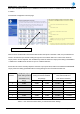
Notes: 1) Approximate loss through combiner filter unit for all bands is 11.5dB
2) Duty Cycle assumption per channel 100%
3) All carriers are to be set to the same level
As indicated in Table 3, an additional 11.5dB of loss has to be added to the RFBE RF output power figure to get
an indication of the output of the 8-Ch combiner filter unit.
The output power level has then to be adjusted negatively by 0.25dB if it is fed through a TLM or 1.2dB through
the standard BPFM.
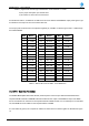
dBm Watts
dBm Watts
dBm Watts
0 1.0 mW
16 40 mW
32 1.6 W
1 1.3 mW
17 50 mW
33 2.0 W
2 1.6 mW
18 63 mW
34 2.5 W
3 2.0 mW
19 79 mW
35 3.2 W
4 2.5 mW
20 100 mW
36 4.0 W
5 3.2 mW
21 126 mW
37 5.0 W
6 4 mW
22 158 mW
38 6.3 W
7 5 mW
23 200 mW
39 8.0 W
8 6 mW
24 250 mW
40 10 W
9 8 mW
25 316 mW
41 13 W
10 10 mW
26 398 mW
42 16 W
11 13 mW
27 500 mW
43 20 W
12 16 mW
28 630 mW
44 25 W
13 20 mW
29 800 mW
45 32 W
14 25 mW
30 1.0 W
46 40 W
15 32 mW
31 1.3 W
47 50 W
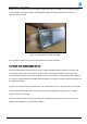
3.3.8 BPFM – Band Pass Filter Module
The DSPbR BPFM (Band Pass Filter Module) is band specific across the pre-determined bandwidth of the
respective RFBE or RFFE. The BBFM is fitted and bolted into the output of the RFBE and input of the RFFE
and is considered as an extension to the respective RFFE or RFBE module. Prior to assembly into a nominated
slot, the BFPM has to be bolted into the respective RFFE or RFBE.
A 2.5mm Allen Key (Hex) tool is required to unfasten or fasten the two modules together as illustrated in Figure
10.
Table 4 – dBm to RF Power in Watts - Cross Reference.