
User's Manual Part 3


DSPbR Series – User’s Manual
Document Number 00000.B Page 44/75
5. Start – Up
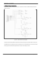
5.1 Connectivity
Ethernet – via RJ45 sockets, refer to Chapter 5.2 for connection details.
RS232 – via serial DB9 connector. The serial interface allows either a local or remote terminal to configure the
DSPbR and access alarm information. This is achieved through pre-configured factory accessible CLI
(Command Line Interface) script.
USB – via USB Type “B” socket. The USB interface allows a local terminal session to configure the DSPbR and
access alarm information. This is achieved through pre-configured factory accessible CLI using hyperterminal in
a TCP/IP session.
Wireless - Multiband Cell Modem (optional). The optional cell modem is capable of using an SMS format to
deliver alarm information to appointed recipients.
5.2 Ethernet Connection Set-up
5.2.1. Web Browser GUI (Graphical User Interface)
The DSPbR utilises an on board web server to provide web browser access to the GUI. This can be accessed
directly connecting via a short Ethernet cable jumper from a laptop/notebook directly to the DSPbR or remotely
via a TCP/IP network.
A standard Ethernet CAT5e jumper terminated with RJ45 connectors is provided with the unit for your
convenience. Use either the rear or front IP Ethernet RJ45 sockets to connect. The DSPbR can be configured
either locally or remotely via either of these IP Ethernet sockets.
Any one of the common web browsers can be used to access the DSPbR GUI.
5.2.2 IP Address
Connect Ethernet jumper cable between laptop / notebook and DSPbR.
Initiate the your preferred web browser such as Internet Explorer, and type in the address field the following
default address; http://192.168.1.200 (factory default address).
Connectivity to the DSPbR is successful when the “log in” page appears.