
User's Manual Part 4


DSPbR Series – User’s Manual
Document Number 00000.B Page 63/75
9.2 Module Replacement
The CSC will auto configure RFFE or RFBE modules of the same type if replaced into the same slot as a
previous RFFE or RFBE module. If the type / band is different, a manual configuration will be required. The
DSP module can also be replaced whilst the DSPbR is powered, however all communications will be
interrupted until such time as the DSP module is connected back into service within the sub rack frame.
9.3 Module replacement self check
To confirm connection and operation of a replaced or new DSP, RFFE or RFBE module, connect to the DSPbR
via the required web browser log in and navigate to the hardware configuration page under the status tab.
For quick reference, the LCD panel on the front of the CSC module will indicate modules detected and enabled
through the sequence described under Chapter 5.4
9.4 PSU Resettable circuit breaker and replaceable fuses
For detailed information on replacing the internal replaceable PSU fuses, please refer to Chapter 3.3.2 of this
manual
An AC mains supply resettable circuit breaker is mounted on the front of the DSPbR between the two fans.
There is no fuse replacement required. Should this AC resettable circuit breaker “pop-out” under operational
conditions; a PSU failure alarm will be activated. It is strongly recommended that before the circuit breaker is
reset, an investigation be made as to the possible reasons why the circuit breaker was activated.
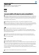
9.5 Fans and Fan filters
Both front mounted cooling fans have removable dust filters, which will require periodic cleaning. These filters
are accessible from the front of the DSPbR buy carefully levering off the plastic fan covers by hand.
Figure 28 – Fan cover removal