
User's Manual Part 2

DSPbR Series – User’s Manual
Document Number 00000.B Page 22/75
When removing or replacing the PSU, ensure to disconnect or connect the in-line plug / socket into the inlet
module.
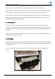
There are three replaceable inverter fuses located within the AC PSU module and in order to check or replace
any of these fuses, the PSU has to be unscrewed from the sub rack frame as previously illustrated in Figure-4,
lever forward on the guide rails using the available handle far enough to access the fuse holders as illustrated in
Figure-5.
All three fuses are identical and listed under the DSPbR part number reference list.
An AC mains supply resettable circuit breaker is mounted on the front of the DSPbR PSU between the two fans.
Should this AC resettable circuit breaker “pop-out” under operational conditions; a PSU failure alarm will be
activated. It is strongly recommended that an investigation be made prior to resetting the circuit breaker as to
the possible reasons why the circuit breaker was activated.
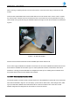
3.3.3 CSC – Central Systems Controller Module
The Central System Controller module is located at the front of the DSPbR and is positioned on the extreme left
hand side as illustrated in Figure-6. An LCD display, a power and two alarm LED’s, mode change button, USB
Type B, TCP/IP RJ45, RS232 socket and CAN bus RJ11 socket are located on face of the CSC module.
DSPbR configuration and diagnostics for all modules is via the CSC module.
Figure 5 – AC PSU fuse location.