
User's Manual Part 2

DSPbR Series – User’s Manual
Document Number 00000.B Page 31/75
3.4.10 TLM - Through Line Module
Where external combining is required, which would typically be in the output channels of the downlink, and
sufficient band pass filtering is provided within an optional external combiner, then a TLM can be bolted to the
output of the RFBE instead of the BPFM. The form dimensions and connector arrangement of the TLM is the
same as the BPFM. It is very important to provide band pass filtering in the external combiner equivalent or
better than the filtering provided by the BPFM in order to maintain the required frequency spectral purity.
3.5 Band and Channel Configurations
The DSPbR architecture facilitates band and channel flexibility with in-field upgradability.
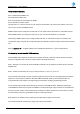
At the rear of the DSPbR sub rack frame are 10 slot apertures numbered sequentially from the left.
SIDE A
SIDE B
DSP
Ref GEN
Power
Input
Slot 1 Slot 9 Slot 10Slot 6Slot 4Slot 3 Slot 7 Slot 8Slot 5Slot 2
View from rear of DSPbR
Figure 12 – Slot Allocation Architecture
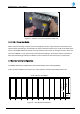
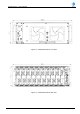
Figure 11 – CXXX-8. 8-Ch Internal Combiner Filter Unit.