
User's Manual Part 2


DSPbR Series – User’s Manual
Document Number 00000.B Page 39/75
Connect an earth bonding cable with a minimum cross section of 16mm² terminated with the appropriate
crimped lug for the 6mm stud and 16mm² copper cable. The 16mm² cable must be identifiable by the green and
yellow coloured PE sheath. Loosen the Hex nut, connect the cable-crimped lug between the two washers and
fasten.
Consideration has to be given to adequate grounding of the RF coaxial cables prior to termination into the
DSPbR, and surge protection for the Ethernet and AC Mains.
Warning: There is no ON/OFF power switch located on the DSPbR.
Where connecting to an AC supply, it is recommended that the DSPbR is turned on via either the wall mount
socket switch, a dual pole isolator switch or dedicated circuit breaker after the mains cord has been fitted.
Where connecting to DC supply, it is recommended that an appropriately rated dual pole DC circuit breaker be
installed. This will assume the role of an ON/OFF switch.
Prior to connecting to either a mains or DC supply, ensure that the RF outputs at the rear of the DSPbR sub
rack frame, whether via an internal or external combiner, are terminated into 50 ohm loads. Once mains power
has been applied to the DSPbR, the outputs of the RFBE’s will automatically activate after approx 45 seconds.
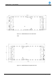
Figure 18 – Sub Rack Frame M6 Earthing Stud