
User's Manual Part 3


DSPbR Series – User’s Manual
Document Number 00000.B Page 43/75
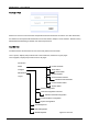
4.6 External / Internal Alarm Interface
At the rear of the chassis protruding from the back of the Ref Gen module is the DB15 female (socket) alarm
interface connector.
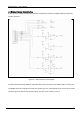
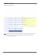
The alarm interface drawing details the respective alarm input and output circuits with the DB15 connector pins.
The DSPbR caters for coupling into the unit and reporting up to four external alarm inputs. All four inputs require
shorting to ground to activate the respective alarm. The open circuit voltage is 12V DC.
Figure 22 – Alarm Interface Circuit Diagram