
User's Manual Part 2


DSPbR Series – User’s Manual
Document Number 00000.B Page 30/75
BPFM’s are used to filter the input to the RFFE’s and filter the output of the RFBE’s. They are factory tuned to
provide a 20MHz pass band and NOT considered field tuneable. No attempt should be made to tune or
optimise tuning of this filter.
An arrow with the letters “UP” on the rear face indicates the module orientation.
3.3.9 Cxxx-8 - 8 Ch Internal Combiner Filter Unit.
The 8-Ch combiner filter unit footprint is across all 8 contiguous RFBE channels, effectively covering 4 slots.
The combiner incorporates built in isolators, a hybrid coupler combiner and a 20MHz wide band pass filter.
Typical insertion loss figure for the 8-Ch combiner inclusive of internal filter is 11.5dB. Although the combiner is
not frequency sensitive within the full 20MHz fixed bandwidth, the combiner is frequency band specific and must
be ordered accordingly.
A single sub rack frame can accommodate two x 8-Ch combiner filter units, one for uplink and one for downlink.
The 8-channel combiner filter unit fits within the spatial confines of the 4RU sub rack frame. The combiner
output connector is an N female.
Please refer to the maximum output power settings of the RFBE when using an 8-Ch combiner filter unit as
detailed under chapter 3.3.7 and illustrated in Table 3.
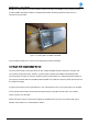
Figure 10 – Bolting RFFE or RFBE onto BPFM