DESKTOP BARCODE PRINTER OS-214plus/OS-2140D/ OS-2140/OS-2140Z/ OS-2140DZ/OS-2140E User’s Manual 9001283 (A) - ENG Website: http://www.satoamerica.
Proprietary Statement This manual contains proprietary information of Argox Information Co., Ltd. It is intended solely for the information and use of parties operating and maintaining the equipment described herein. Such proprietary information may not be used, reproduced, or disclosed to any other parties for any other purpose without the expressed written permission of Argox Information Co., Ltd.
For Support Table of Contents For any issues or questions, contact SATO America, Inc. using the contact information shown here. Safety .........................................................................................2 Getting Started ................................................................... 6 Unpacking ..................................................................................6 Package Contents ...................................................................
Media Sensor .......................................................................61 Thermal Print Head..............................................................61 Replacing the Thermal Print Head.......................................64 Important notice during TPH replacement ....................66 Technical Reference.........................................................67 General Specifications .............................................................
Connecting the Power Supply Connect the power supply as below. WARNING! Do not operate the printer and power supply in an area where they can get wet. Make sure the power switch is in the "O" position. 1. Insert the barrel connector of the power supply into the power jack on the back of the printer. Note the location of the power jack for different models in the diagrams below. 2. Insert the separate power cord into the power supply. 3. Plug the other end of the cord into an AC electrical outlet.
Power Cord OS-2140E OS-214plus 9 10
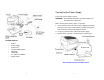
Getting to Know Your Printer The illustrations that follow describe the printer’s parts, features, controls, and indicators.
Controls and Indicators Ribbon Supply Holder Thermal Print head The printer’s controls and indicators are shown in the diagram below. The following table explains control and indicator functions.
Loading Ribbon and Media Control / Indicator Function Power Switch Off: turns off power Note: Turn power off before connecting or disconnecting cables Power Indicator Ready Indicator Feed Button On: turns on normal operation Green light shows the power-on Light off shows the power-off Blinking light indicates error has occurred Green shows printer is ready to operate Blinking light indicates printer is paused or data transferring Seagull driver status monitor Press to
Media Compartment Print Head Module Release Lever Release Lever 4. Unwrap the ribbon roll pack and separate the ribbon roll and the bare core. 5. Attach the edge of the ribbon on the bare core and wind it a little bit onto the core. 6. Insert the ribbon roll into the supply holder. (First snap in the left side and then the right side.
7. Turn back the print head module and then insert the bare core into the pick-up holder. (First snap in the left side, and then the right side.) 8. Turn the wheel of the print head module to ensure the ribbon is tightly wound. 9. Press down the print head module firmly until you hear a snap.
2. Remove the media hanger. Loading Media The OS-214plus/OS-2140D/OS-2140/OS-2140Z/OS-2140DZ/ OS-2140E printers offer Two different loading modes: standard or with a cutter. Standard mode allows you to collect each label freely. Cutter mode automatically cuts the label after it prints. Media Compartment Media Hanger Standard Mode 1. Lift the top cover to expose the media compartment. 3. Load the media roll onto the hanger from left to right.
4. Click the media hanger back into the media compartment. 5. Align the media roll to the left end. 6. Move the shield from right to left until it leans against the media. 7. Unlatch the print head module. 8. Hold the print head module upright with one hand to allow the media to pass under it. Lead the media through the media guides with the other hand. 9. Lead the media over the platen roller.
Cutter Mode 10. Put the print head module down and press down firmly until you hear a snap. 11. Close the top cover and turn on the printer or press the "FEED" button if the printer is already on. Note: For Cutter mode you must first install the cutter and add the cutter baby board to J16 on the main board. Please refer to Appendix I. Follow Steps 1 to 8 listed in Standard Mode above. Print Head Module 9. Thread the media over the platen roller, then route the media through the slot of the cutter module.
11. Close the top cover and turn on the printer or press the "FEED" button if the printer is already on. Note: The "FEED" button does not make the printer cut. Cutting occurs only when the software is properly set. Calibration and Configuration This section discusses calibration, printing configuration and resetting the printer to factory defaults. Performing Calibration and Configuration 1. 2. 3. 4. 5. Turn off the printer power.
Resetting to Factory Default Settings 1. Turn on the printer and wait for 5 or more seconds. 2. Press the "Feed" button for 10 seconds, and the "Ready" indicator and "Power" indicator will go off in order. 3. When the two indicators relight, release the feed button. 4. The printer feeds approximately 3 ~5 blank labels, and then resets to the factory defaults. Note: Revise the factory default settings that stored in flash, even if turn off the power source cannot be eliminated.
Serial (RS-232) Interface Requirements Serial Cabling Requirements The required cable must have a nine-pin "D" type male connector on one end, which is plugged into the mating serial port located on the back of the printer. The other end of the signal interface cable connects to a serial port on the host computer. Data cables must be of fully shielded construction and fitted with metal or metalized connector shells.
Parallel Interface Requirements Ethernet Interface The required cable (IEEE 1284-compliant is recommended) must have a standard 36-pin parallel connector on one end, which is plugged into the parallel port located on the back of the printer. The other end of the parallel interface cable connects to the printer connector at the host computer. For pin-out information, refer to the Reference Technical Information, Interface Specification.
Ethernet Status/Activity Indicators LED Status Both Off Green LED Amber LED Description No Ethernet link detected Speed LED On: 100 Mbps link Off: l0 Mbps link Link/Activity LED On: link up Off: link down Flash: activity Communicating with the Printer The bundled printer driver can be applied to all applications under Windows 2003/ XP/ Vista/ Windows 7, supporting 32-bit/ 64-bit operation systems.
USB port on the printer and on the PC. 2. Turn on the printer. If the printer supports Plug-and-Play, and you have successfully connected it using a USB cable, then the Windows Add Hardware Wizard will automatically detect the printer and display a dialog that allows you to install a driver. Click Cancel and do not install the driver using this wizard. 3. Prepare the documentation and software CD-Rom from printer package and then install to CD-Rom drive of your computer.
6. Enter Printer name (i.e. Argox OS-2140 PPLA) and select "do not share this printer”, and click "Next". Argox OS-2140 PPLA Argox OS-2140 PPLA Then click “Next.
7. Check all the data on the showing screen, if it is correct, click "Finish". 8. After the related files have been copied to your system, click "Finish". Argox OS-2140 PPLA USB002 Installing printer ‘Argox OS-2140 PPLA’… Argox OS-2140 PPLA 7.1.
9. After driver installation is complete, click "Close". The driver should now be installed. Installing the Printer Driver 1. Turn off the printer. Plug the power cable into the power socket on the wall, and then connect the other end of the cable to printer's power socket. Connect the USB cable, Serial cable, or Ethernet cable to the proper port on the printer and on your computer. Installed printer Argox OS-2140 PPLA 2.
3. Under OS-2140 product selection prompt, choose Seagull Driver version and then start installation: 4. On the prompt, Windows Printer Driver, select “I accept…” and click "Next". Instead of the flash prompt above, another way to install Seagull driver is to run the DriverWizard utility from the Installation Directory where the Seagull driver files are located.
6. Click "Finish". 5. Assign the directory to keep Seagull driver, (for example: C:\Seagull) and click "Next".
7. Select Install printer drivers and Click "Next" 8.
9. Select the port of the printer and click "Next". 10. Enter Printer name (i.e. Argox OS-2140 PPLA) and select "do not share this printer”, and click "Next".
11. Check all the data on the showing screen, if it is correct, click "Finish". 12. After the related files have been copied to your system, click "Finish". Argox OS-2140 PPLA USB001 Installing printer ‘Argox OS-2140 PPLA’… Argox OS-2140 PPLA 7.1.
13. After driver installation is complete, click "Close". The driver should now be installed. Troubleshooting Normally, when the printer is in not working properly, the "Power" LED blinks continuously; while printing and communication between the host and printer stops. LED Diagnosis Installed printer Argox OS-2140 PPLA Power and Ready LEDs blinking continuously indicates printer errors.
LED Indicators: Power and Ready LEDs blink alternately LED Indicators: Only the Ready LED blinks Power LED ON OFF Power LED Ready LED ON ON ON OFF Ready LED OFF ON Possible Problems Solutions Ribbon out Supply the ribbon roll Ribbon jam Recover the jam Ribbon sensor error Replace ribbon sensor Remarks Not applicable to direct thermal type.
Miscellaneous If the host shows "Printer Time out" 1. Check if the communication cable (parallel or serial) is connected securely to your parallel or serial port on the PC and to the connector on the printer at the other end. 2. Check if the printer power is turned on. If the data has been sent, but there is no output from the printer. Check the active printer driver, and see if Seagull driver for your Windows system and the label printer has been selected.
TPH Cleaning Interval: Caring for Your Printer Adhesives and coatings of media can over time transfer onto the printer components along the media path including the thermal print head and media sensor. This build-up can accumulate dust and debris. Failure to clean the print head, media path, and media sensor could result in inadvertent loss off labels, label jams and possible damage to the printer.
Replacing the Thermal Print Head 1. 2. 3. 4. Switch off the power and wait for both LEDs to go off. Unlatch the print head module. Remove the ribbon. Push the print head firmly into the casing and shift it to the left. It will release from the module. Special Caution: Warranty of print heads will be void if print head serial number is removed, altered, defected, or made illegible, under every circumstance. 63 5. Disconnect the print head cable.
6. Disassemble the print head and the mounting bracket by releasing screws. 7. Replace with a new print head. Reassemble the print head module in reverse order. Be careful not to touch the print head elements. 65 Important notice during TPH replacement 1. Heater line should NOT be touched by bare hands to prevent any damage caused by ESD or corrosion. 2. Surface of heaters should NOT be hit or scratched by sharp or hard things to prevent any damage by scratch. 3.
Technical Reference General Specifications Specification Printing method Printing resolution Printing speed Printing length Printing width Memory CPU type Media sensor Operation interface Communication Interface Fonts OS-2140D Direct Transfer OS-2140 OS-214plus Direct Transfer/Thermal Transfer 203 dpi (8dots/mm) 2~3ips(51~76mm/s) Up to 4ips (102mm/s) Max 43”(1092mm) Max 100” (2540mm) Max 4.
2D Barcodes Graphic Emulation Software-Label editing Software-Utility Media Type Media Ribbon Dimensions Weight Power Source Operation Environment OS-2140 & OS-2140D: PPLA/PPLB/PPLZ: MaxiCode, PDF417, Data Matrix (ECC 200 only), QR code, Composite codes OS-214plus: PPLA: PDF-417, MaxiCode, Data Matrix (ECC200 only) ,QR Code, Composite codes PPLB: MaxiCode, PDF-417, QR Code, Composite codes OS-2140 & OS-2140D: PPLA/PPLB: PCX, BMP, IMG, HEX,GDI, Binary raster(PPLB Only) PPLZ: GRF, Hex and GDI OS-214plus
Fonts, Bar Codes and Graphics Specification The specifications of fonts, bar codes and graphics depends on the printer emulation. The emulations PPLA, PPLB and PPLZ are printer programming languages, through which the host can communicate with your printer.
Printer Programming Language Z, PPLZ Programming Language Internal fonts Symbol sets (Code pages) Soft fonts PPLZ 8 (A~H) fonts with different point size. 8 AGFA fonts: 7 (P~V) fonts with fixed different point size (can’t scale). 1 (0) font with scaling point size. USA1, USA2, UK, HOLLAND, DENMARK , NORWAY, SWEDEN/FINLAND, GERMAN , FRANCE1, FRANCE2, ITALY, SPAIN, MISC, JAPAN, IBM850. Notes: 1. The bare core for the ribbon must be 11 cm in length. It should have two opposite slits at two ends.
Serial Interface Specifications The RS232 connector on the printer side is a female, DB-9. USB Interface This is port complies with USB 2.0 Full Speed. Connector Terminal Pin Assignment Pin Signal 1 VBUS 2 D- 3 D+ 4 GND 2 1 3 4 Description 5V Differential data signaling pair Differential data signaling pair + Ground Pin 1 2 3 4 5 6 7 8 9 Direction In Out Out In Out T Definition Shorted to Pin 6 RxData TxData N.C.
Ethernet Parallel (Centronics) The following port complies with Ethernet communication. The parallel port is a standard 36-pin Centronics, which complies with IEEE 1284 standard (compatibility mode).
Connection with host Host 25S Printer 9P (PC or compatible) Host 9S Printer 9P (PC or compatible) DTR 20 DSR 6 TX 2 RX 3 CTS 5 RTS 4 GND 7 DTR 4 DSR 6 TX 3 RX 2 CTS 8 RTS 7 GND 5 …… …… …… …… …… …… …… 1 DSR 6 DTR 2 RX 3 TX 7 RTS 8 CTR 5 GND …… …… …… …… …… …… …… 1 DSR 6 DTR 2 RX 3 TX 7 RTS 8 CTS 5 GND Printer Pin 2- RxData ……… Pin 3- TxData ……… Pin 5- Ground ……… Terminal/Host TxData RxData Ground In general, as long as the data quantity is not too large and you use Xon/Xoff as flow control, it will
Appendix I - Installing the Cutter 1. Turn off the printer power and unplug the power cable and Serial / USB cable. 2. Remove the top cover. 3. Remove the two screws under the base housing. 4. Remove the whole print head assembly by releasing the 4 screws at its feet. Print Head Assembly 5. Add the cutter baby board to J16 on the main board.
Appendix II - Installing the Extension Card 6. Secure the four screws attaching the cutter. Extension Card designated for all optional extension modules. For example, RTC card and Add-on card. Install the extension card into the printer as follows: 1. Turn off the printer power. 2. Remove the top cover. 3. Release the two screws at the bottom of the base housing. Cutter 7. Plug the cutter's connector into the PCB's header connector (J9). 8. Reattach the print head assembly by securing the 4 screws. 9.
4. Remove the middle cover. 5. Mount the extension card to J14 on the main board. Slot for Extension card 6. Click back the middle cover. 7. Secure the two screws for the base housing. 8. Click the top cover into place.