
Service manual


35
TTP-244 Plus Bar Code
Printer Service Manual
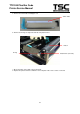
5.6 Testing Sensors
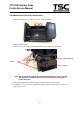
A. Checking Ribbon Sensor
Switch the multimeter to the DC gear. Connect the black wire to DC GND, and the red
wire to PIN2 of JP18.
1. When ribbon is detected between TX and RX of the ribbon sensor, the measured
voltage should be 5 Vdc.
2. When ribbon is not detected between TX and RX of the ribbon sensor, the measured
voltage should be 0 Vdc.
The ribbon sensor is normal if the checking complies with the two cases above. Or else,
the ribbon sensor is out of order.
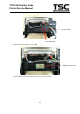
B. Checking DC Motor Encoder Sensor
Switch the multimeter to the DC gear. Connect the black wire to DC GND, and the red
wire to PIN4 of U35.
1. When gap of the gear box is detected by the DC motor encoder sensor, the
measured voltage should be 5 Vdc.
2. When gap of the gear box is not detected by the DC motor encoder sensor, the
measured voltage should be 0 Vdc.
The DC motor encoder sensor is normal if the checking complies with the two cases
above. Or else, the DC motor encoder sensor is out of order.
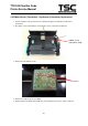
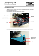
C. Checking Black Line Sensor
Switch the multimeter to the DC gear. Connect the black wire to DC GND, and the red
wire to PIN2 of U2. Load black line label on the printer.
1. When black line is detected by the black line sensor, the measured voltage should
be 3 Vdc.
2. When black line is not detected by the black line sensor, the measured voltage
should be 0 Vdc.
The black line sensor is normal if the checking complies with the two cases above. Or
else, the black line sensor is out of order.