Checking Your Box Receiving the box of your printer, you are advised to check first for the possible shipping damage. There are two ways you can do it: 1. Inspect the outer appearances of both the box and the printer for possible damage. 2. Raise the top cover of the printer to see if the media compartments are in order. If damages did occur, immediately file the claim to the shipping company for settlement.
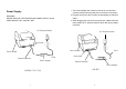
Power Supply WARNING: NEVER OPERATE THE PRINTER AND POWER SUPPLY IN AN AREA WHERE THEY CAN GET WET. 1. The Power Adapter has a barrel connector on one end that must be inserted into the power jack on the back of the printer. 2. Plug the other end of the cord into an appropriate AC electrical outlet. 3. When plugging the connector into power jack, please leave the power switch at "O" position and don't touch the 36 pin parallel connector.
Parts and Features (OS-214, OS-314) Top Cover Ribbon Supply Holder Thermal Printhead H Cover Platen Roller Power Switch Power Indicator Ready Indicator Power Switch Feed Button Peel-Off Option Ribbon Pick-up Holder Cutter Option Media Hanger Release Levers Cutter White Plastic Roller 5 6
Parts and Features (OS-203 , OS-204) Top Cover Thermal Printhead H Cover Power Indicator Power Switch Ready indicator Feed Button Peel-Off Option Cutter Option Media Hanger Release Levers Platen Roller White Plastic Roller 7 Cutter 8
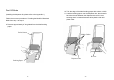
Loading the Ribbon (OS-214, OS-314) Media Compartment Note: This section is not applicable to the direct thermal printing. 1. Lift the top cover to expose the media compartment. 2. Unlatch the print head module by pushing the two white release levers on the sides toward the rear. 3. Turn over the print head module to expose the ribbon supply holder.
4. Unwrap the ribbon roll pack and separate the ribbon roll and the bare core. 5. Attach the edge of the ribbon on the bare core and wind it a little bit onto the core. 6. Insert the ribbon roll into the supply holder. (First snap in the left side and then the right side.) 7. Turn back the print head module and then insert the bare core into the pick-up holder. (First snap in the left side, then the right side.
8. Turn the wheel of the print head module to ensure the ribbon is tightly wound. 9. Press down the print head module firmly till you hear a snap. Loading the Media OS Series printers can be operated in three different options: standard, peel-off, or with a cutter. - Standard mode allows you to collect each label freely. - In peel-off mode, the backing material is being peeled away from the label as it is printed. After the former label is removed, the next one will be printed.
2. Remove the media hanger. 3. Load the media roll onto the hanger from the left. Media Compartment 4. Click the media hanger back to the media compartment. 5. Move the media roll to the left end. 6. Move the shield to the left next to the media.
7. Unlatch the print head module. 8. Hold the print head module upright with one hand to allow the media pass under it. Lead the media through the media guides with the other hand. 9. Lead the media over the platen roller. 10. Turn back the print head module and then press it down firmly till you hear a snap. 11. Close the top cover and turn on the printer or press the feed button if the printer is already on.
Peel Off Mode (Installing the dispenser kit, please refer to the Appendix I ) Follow the common procedure of "Loading the Media"of Standard Mode from step 1 to step 8. 10. Trim the edge of the label backing paper with scissor or knife. 11. Lead the backing paper over the dispenser bar, then thread it back into the slot between the dispenser bar and H cover, ensuring that it is inserted between white plastic roller and platen roller. 9. Remove approximately 6" long labels from the label backing paper.
12. Press "FEED" button and the label backing paper will come out from the slot under the H cover. 13. On OS-203 Peel-Off mode, powered on status, in case of improper installation, just keep pressing the "FEED" button to back-feed the label stock to re-install it. 14. To remove any slack, just rewind the media onto the roll.Press down the print head module firmly. 15. Close the top cover and turn on the printer or press the "FEED" button if the printer is already on.
Cutter Mode ( Installing the cutter, please refer to Appendix II ) Follow the same procedure as "Loading the Media" from step 1 to step 8. 9. Thread the media over the platen roller, then route the media through the slot of the cutter module. 10. Press down the print head module firmly. 11. Close the top cover and turn on the printer or press the "FEED" button if the printer is already on. Note: The "FEED" button will not drive the printer to cut.
Operator Controls Power Switch Controls printer power On-normal operation Off-the power should be turned off before connect or disconnect the communication cables and power cables Top Cover Feed Button Advance the label media to first printing position Press-to advance a label Press-takes the printer out of a "pause" condition Press-back feed the label to correct label installation, in case that label is not properly installed.
Performing Calibration 1. Keep pressing the feed button while turning on the power, until the printing motor becomes activated. 2. The calibration has been performed while the printer automatically feed label stock for certain length. Note: This step is very important and must always be carried out whenever media is being changed. Failure to do so will result in miss-detection of the label sensor. Printing Configuration Report Resetting the Printer to Factory Default Settings 1.
Hooking up the Printer and the Computer OS-204/214/314 Note : The power supply barrel connector must be inserted into the power jack on the back of the printer before connecting the communication cables. This printer comes with both a nine-pin Electronics Industries Association (EIA) RS-232 serial data interface (for OS-203, it is six pin) and a standard Centronics parallel interface. In either case, you must supply the required interface cable for your application.
Parallel Interface Requirements Communicate with the Printer The required cable (IEEE 1284-compliant is recommended) must have a standard 36-pin parallel connector on one end, which is plugged into the parallel port located on the back of the printer. The other end of the parallel interface cable connects to the printer connector at the host computer. For pinout information, refer to the Reference Technical Information- Interface Specification. Serial and Parallel Cabling Requirements.
Installing Driver 1. Click the "Start" button. 2. Select "Settings", then select "Printers" and double click the "Add Printer" icon. Click "Next". 3. Click the "Network" or "Local" button and click the "Next" button. 4. Click "Have Disk", click the pull-down menu to select CD ROM driver path. 5. Click "Browse" button. 6. Select the proper directory for installation: -WIN98 -WIN2000 -NT4.0 -XP 7. The driver name "Label Dr. 200" (or Label Dr.300) will appear in the "List of Printers", click "Next". 8.
Set the Parameters For Win 98 After installing the driver, you can follow the path below to set parameters: Start →Settings→ Printers→ Label Dr.→ Properties ▀ Ports Properties menu The parameters include: Ports Select the IO port to link with the printer. The port may be one of parallel (LPT), serial (COM), network port or file. → Click "Details". → Select the IO port. → Click "OK". Paper size Select the proper size on the menu. If there is no desired size, select "Custom" to define the paper size.
▀ Output bin (Accessory setting) Properties menu ▀ Create a new size Properties menu → Click "Paper". → Select "Custom". → User-Define size. → Set up a new size. → Click "OK". → Click "Paper". → Click "more option". → Select Enable/without cutter, peeler. → Click "OK". ▀ Print quality (Speed) Properties menu → Click "Device Options". → Select parameters. → Click "OK".
For Win 2000 ▀ Orientation Printing Reference menu ▀ Ports Properties menu → Click "Layout". → Select "Portrait" or "Landscape". → Click "OK". → Click "Ports". → Select the IO port. → Click "OK". ▀ Paper size ▀ Copies ▀ Media choice (Accessory setting) ▀ Paper/Output (Speed) ▀ Print quality (Darkness) Printing Reference menu ▀ Paper source (Media type) Back to Printers menu → Right click to get pop-up menu. → Select "Printing Reference". → Click "Paper Quality" select media type. → Click "OK".
▀ Create a new size Printer menu For NT 4.0 → Right click to get popup menu on empty space. → Select "Server Properties". → Enter a form name for the new form in "Form description for". → Reset the paper size in the specific squares of the "Measurements". → Click "OK". ▀ Ports Properties menu → Click "Ports". → Select the IO port. → Click " OK". ▀ Paper size ▀ Orientation ▀ Paper source (Media type) ▀ Copies ▀ Media choice (Accessory setting) Printer’s menu → Right click to get pop-up menu.
For Win XP ▀ Paper/Output (Speed) ▀ Print quality (Darkness) Default Document menu ▀ Ports Properties menu → Click "Advanced". → Click each item to select desired parameter. → Click "OK". → Click "Ports". → Select the IO port. → Click "OK". ▀ Create a new size Please refer to the procedures of ”Create a new size” on Win 2000. ▀ Paper source (Media type) Back to Printers menu → Label Dr. → Right click to get pop-up menu. → Select "Printing Reference". → Click "Paper Quality". → Select media type.
▀ Orientation Printing Reference menu ▀ Create a new size Printer menu → Click "Layout". → Select "Portrait" or "Landscape". → Click "OK". → Right click to get pop-up menu in blank space. → Select "Server Properties". → Enter “Form name” for the new form. → Reset the paper size in the specific squares of the "Form description" → Click "OK". ▀ Paper size ▀ Copies ▀ Media choice (Accessory setting) ▀ Paper/Output (Speed) ▀ Print quality (Darkness) Printing Reference menu → Click "Layout".
B. Power and Ready LEDs blink alternately Troubleshooting Normally, when the printer is in abnormal condition, the "POWER" LED will keep blinking. The printing work and the communication between the host and printer will stop. To understand the problem, please check both LEDs first: Power LED ON OFF Ready LED OFF ON Possible Problems Ribbon out Ribbon jam Ribbon sensor error Solutions Remarks Not applicable to Supply the ribbon roll direct thermal type. Recover the jam Replace the ribbon sensor A.
D. Miscellaneous The host shows "Printer Time out" 1. Check if the communication cable (parallel or serial) is connected securely to your parallel or serial port on the PC and to the connector on the printer at the other end. 2. Check if the printer pow er is turned on. If the power cord is connected, the power switch is at position "I" and the power LED has still not illuminated, check the fuse inside the power adapter case. The data has been sent, but there is no output from the printer.
Caring for Your Printer Replacing Thermal Print Head Clean the following areas of the printer after 8 rolls of label stocks have been used. In each case, use a cotton bud dampened with alcohol. Do not soak the cotton bud excessively. 1. Switch off the power and wait for both LEDs to go off. 2. Unlatch the print head module. 3. Remove the ribbon. 4. Push the print head firmly into the casing and shift it to the left. It will release from the module. 5. Disconnect the print head cable. 6.
Reference Technical Information 1.General Specifications Model Model OS-314TT OS-214 /214 Zip Print method Direct thermal Direct thermal and thermal transfer Resolution 203 DPI (8 dots/mm) 300 DPI (12 dots/mm) Maximum print width 2.83 in. 4.1in. 4.25 in. (72mm) (104 mm) (108 mm) Maximum print 10 in. 8 in. 14 in. (356mm) length (254mm) (203mm) Maximum print 3.
Model Model OS-314TT OS-214 /214 Zip Maximum label 4.3 in.(109mm) outside diameter, 1 in.(25 mm) inside roll diameter diameter Label indexing Black stripe and gap Ribbon types Wax, Wax/Resin and Resin Ribbon size X OD 1.45 in. (37 mm); ID 0.5 in. (12.7mm); Length11 Specification Dimension Weight Electrical Operating temperature Storage temperature Humidity Model Model OS-203 OS-204 W5.3 x D9.0 x H6.4 in. 1.2Kg (2.6 lbs) FCC class A 21VAC W7.3 x D10.9 x H6.
2.Fonts, Bar Codes and Graphics Specification Printer Programming Language B, PPLB The specifications of fonts, bar codes and graphics depend on the printer emulation. The emulation is a printer programming language, through which the host can communicate with your printer. There are two printer programming languages for models 203/204/214/314, they are PPLAand PPLB.
3.Interface Specifications Serial For OS-204/214/314, the RS232 connector on the printer side is a female, DB-9. Pin 1 2 3 5 6 7 8 9 Direction In In Out Out Out In Out Definition DSR RxData TxData Ground DTR RTS CTS +5V Note : Pin 9 on OS-204/214/314 and pin 1 on OS-203 are reserved for KDU(keyboard device unit), therefore do not connect these pins if you are using a general host like a PC.
The simplest way to connect to other hosts (not PC compatible) or terminals is: Printer Pin 2- RxData Pin 3- TxData Pin 5- Ground ……… ……… ……… Terminal/Host TxData RxData Ground In general, as long as the data quantity is not too large and you use Xon/Xoff as flow control, it will be problem free. Baud rate: 2400, 4800, 9600, 19200 and 38400. (programmable by command) Data format : always 8 data bits, 1 start bit and 1 stop bit.
Appendix I - Installing Dispenser Kit 4.ASCII TABLE NUL SON STX FF ! " # $ % & ‛ ( ) * +; , 0 1 2 3 4 5 6 7 8 9 : ; < @ A B C D E F G H I J K L P Q R S T U V W X Y Z [ \ ' a b c d e f g h i j k 1 P q r s t u v w x y z { I CR SO SI . / = > ? M N O ] ^ _ m n o } ~ DEL XON XOFF NAK ACK BEL BS LF ESC RS US 63 1. Turn off the printer power and unplug the printer. 2.
6. Route the peeler sensor cable through the guides along the left side of the top cover. 7. Fix the sensor cable and sensor board with Loctite-444 instant adhesive or equivalent. Sensor Cable Middle Cover 8. Release the two screws at the bottom of the base housing. 9. Remove the middle cover. 10. Take off the H Cover. 11. Tape the direction label on the top of the H cover with the arrow sign heading toward the opposite of you. H.
Base Housing 12. Release the screw on the left bracket of the chassis. 16. Hook the dispenser bar on the brackets of the chassis, positioning it above the white roller. Ensure that the dispenser bar is paralleled with the black platen roller and it's long thinner end is at the left. 17. Secure back the screw on the left bracket of the chassis. 18. Guide the sensor cable connector through the hole on the upper left corner of middle cover. Screw Screw 13. Unlatch the print head module.
19. Click the top cover back to the middle cover. 20. Insert the sensor connector into its receptacle on the main logic board of the base housing. 21. Click the middle cover back to the base housing. First click in the front part then the rear. 22. Secure the two screws at the bottom of the base housing. Appendix II - Installing the Cutter 1. Turn off the printer power, unplug the power cable and Centronics / Serial cable. 2. Remove the top cover. 3. Remove two screws at base housing. H.
4. Remove the whole print head assembly by releasing 4 screws at its feet. 5. Add a driver IC to U19 on the main board. 6. Secure four attached screws for the cutter. Print Head Assembly Cutter 7. Plug the cutter's connector into the PCB's header connector (JP13). 8. Reinstate the print head assembly by securing back the 4 screws. 9. Click back the middle cover. 10. Secure two screws back at base housing. 11. Click back the top cover.